Get Clear Insights Into Cloudy Water With The Open Colorimeter

A basic scientific tool for chemistry and biology is a colorimeter device used to measure which wavelengths of light a particular sample solution absorbs. Some applications of colorimeters are measuring pH or chlorine levels, measuring pollutants, such as oil or pesticides, and, in some cases, can even be used to measure RNA/DNA concentrations. Even most washing machines today have a specialized colorimeter sensor, of sorts, to measure turbidity (cloudiness) to provide feedback on the cleaning process. To help in building your home scientific lab, [IORodeo] has released an Open Colorimeter.

A blown out diagram of the Open Colorimeter showing the 3d enclosure, the PyBadge, the LED board and sensor along with text describing each element

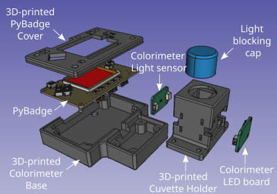
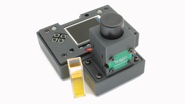
The Open Colorimeter is a self-contained device that accepts cuvettes filled with liquids for testing. The basic structure is an LED mounted onto a board that shines through the cuvette filled with a sample that is then measured at the other end by a TSL2591 color sensor. The Open Colorimeter has separate specialized LED boards for a range of wavelengths from 470nm to 630nm and incorporates a PyBadge that serves as the main microcontroller, as well as display and input.

[IORodeo] has done extensive documentation on the assembly, usage, and testing of the device. They have also provided protocols for the measurement of Ammonia, Nitrate, Nitrite, and Phosphates in addition to providing resources for absorption profiles of many other substances. All files relating to the 3D enclosure, firmware source code, schematics and Gerbers are provided under an open source hardware compatible license. For those not wanting to build it themselves, [IORodeo] is offering them for sale.

This isn’t the first time we’ve featured colorimeters, with some building a DIY version and others using it in a Tricorder project. The Open Colorimeter is a nice addition to this list and is ready for hacking and extending!

HunterCatNFC tool

Hunt Down NFC Signals With This NFC Multi Tool

NFC hacking can be a daunting task with many specialized tools, a proliferation of protocols, and a multitude of different devices. [ElectronicCats] has done a lot of work to try to make this investigation accessible by creating an open-source, hardware-certified NFC tool called the HunterCatNFC that can read and emulate a multitude of NFC devices.

The HunterCatNFC device is meant to be portable and self contained, with LED indicator lights that can give information about the various modes, and feedback about what data is being received. At its core, the HunterCatNFC has an NXP PN7150 NFC controller chip to handle the NFC communication. The main processing controller is a Microchip SAMD21 which also provides USB functionality, and the whole device is powered by a 3.7V 150mAh Li-ion battery.

The HunterCatNFC has three main modes, ’emulation’, ‘read/write’ and ‘peer-to-peer’. Emulation mode allows the HunterCatNFC to mimic the functionality of a passive NFC device, only responding when an NFC reader issues a request. The read/write mode allows it to emulate an NFC reader or writer, with the ability to communicate with nearby passive NFC devices. The peer-to-peer mode gives the device the ability to have two way communication, for instance, between two HunterCatNFC devices.

We’ve covered NFC hacking before, including the Flipper Zero. The HunterCatNFC is a fine addition to the NFC hackers arsenal of tools with some very nice documentation to learn from. For those not wanting to send out their own boards to be printed and assembled, [ElectronicCats] has them for sale.

Video after the break!

Continue reading “Hunt Down NFC Signals With This NFC Multi Tool”

A picture of the JagerMachine consisting of rectangular, desktop sized drink serving machine with a wooden varnish, a 3.5 inch touchscreen on the front face on top and a cavity with a shot glass in it, lit up by blue leds, with liquid pouring into it.

Shoot An Email To Get A Shot

[_Pegor] wanted to create a shot pouring machine for their friends birthday. Unfortunately, the build wasn’t done in time, but at least the JagerMachine is finished now so that others can use it.

The JagerMachine has a peristaltic pump that moves liquid from a reservoir hidden in the back of the machine to the glass in front. The machine has a 3.5 inch DSI touch screen display for user input and a WS2812B LED ring for creating a small light show when the drinks are served. A 3.3 V to 5 V level shifter is used to power the LED ring and a motor driver module is used to drive the peristaltic pump motor. It looks like there’s a “shot glass detection” feature that uses a 3D printed mini platform with a notch for a magnet so that when a glass is placed on top of it, the hall sensor can detect the presence of the nearby magnet.

Part of the charm of this project is the software stack on the Raspberry Pi that allows for novel interaction, including being able to serve drinks from the receipt of emails. Using the Raspberry Pi as the controlling device allows for this rich set of interfacing options, including easily allowing the ability to drive the LEDs, detect the presence of the shot glass, along with establishing network connectivity. The setup procedures are all documented in the repository for anyone wanting to see how this type of functionality might transfer to their own project.

Drink mixing robots are, of course, a thing. ranging from small and cute to full shelf.

A cyclotron clock display, mounted on a wooden base. There are two stepper motors exposed on either side. There is a panel installed in the wooden base with a red button on the left, two knobs and four smaller buttons in a two by two grid on the right.

A Flipping, Perpetually-Rotating Clock

Clocks are a mainstay of hackers and makers, as they provide a way to explore creative designs while still maintaining a functional aspect to the project. [Brett Oliver] follows this tradition in making a cyclotron clock that uses a perpetual rotating digit concept from a 1900s desk flip calendar.

An exploded view of one of the flip calendar digit display, showing how the tiles fit into the chamber.

Each digit of the clock has a rotating chamber that’s big enough to fit a group of tiles inside that have digits printed on either face. The tiles are sized and stacked in such a way that the rotation of the chamber allows the next tile to slide in front of the old one. Specific digits are revealed by rotating the chamber a number of times.

Each of the four digits positions has a 28BYJ-48 stepper motor to rotate the chamber, with each motor being driven by a ULN2003 driver module. The main microcontroller is a ESP32 WROOM, and an I2C compatible DS3231 real time clock (RTC) module keeps time. All of the motors are driven off of an LM2596 module that provides 7 V, while the ESP32 and RTC are powered from a USB connector.

The different modes and the ability to set time is done through a panel that has various buttons and knobs. The whole clock is mounted on a custom wooden base that has cutouts for the panels and cabling. [Brett Oliver] has done a great job of documentation, going into detail about the mechanics and electronics of the build. Design files, including STLs of the various components, are also available for download. Be sure to check out the video after the break.

We’ve featured a flip calendar with a similar operating principle before which clearly shows the inner workings of the mechanism.

Continue reading “A Flipping, Perpetually-Rotating Clock”

A three picture sequence, with the first picture being a woman in a blue lit up prom dress touching a wand to her hand, the second picture being a woman in a pink lit up dress touching a wand to her hand and the third picture being the same woman in a lit up pink prom dress holding a blue glowing star wand over her head

Be The Star Of The Evening With This Light Up Prom Dress

[Kellechu] went full parent beast mode by creating a prom dress for her daughter. This incredible build is a tour-de-force of DIY crafting, combining sewing, electronics, 3D printing and programming.

The dress skirt is made of tulle that allows for the LED strip underneath to diffuse through. The top bodice is made of fiber optic fabric sewn between the fabric form with the dangling fiber optic threads grouped into bundles. The dangling fiber optic bundles were then inserted and glued into “out caps” that forced the strands to sit next to a NeoPixel LED. A 20 NeoPixel “Dots Strand” strip was strung around the waist line, affixing 12 of the NeoPixels with an “out cap” to light up the fiber optic bodice. The remaining NeoPixels were outfitted with a diffuser cap and hung lower to light up the tulle skirt portion of the dress.

A bodice of a prom dress hanging on a form with fiber optic fabric bundles dangling underneath with some of them installed into a NeoPixel "Dots Strand" strip installed along the waist line

A wand was 3D printed and housed with an RFM69HCW Packet Radio M0 Feather, a NeoPixel LED color ring and a TCS34725 Flora color sensor powered by a 2.2 Ah 3.7 V LiPo battery. Another RFM69HCW Packet Radio M0 Feather was placed in the dress to be able to receive messages from the wand so that the sensed color could be transmitted and the LED strip could be updated with the sensed color. The dress portion was powered by a 10 Ah 3.7 V LiPo, with the battery and electronics fitting snugly into yoga bike shorts with side pockets.

[Kellechu]’s Instructable is full of details about the process and is worth checking out. For example, [Kellechu] goes into detail about the troubles and care taken when dealing with the different media, making sure to avoid ironing the fiber optics so as not to melt the lines and experimenting with different sewing needles to limit the amount of dead fibers as collateral damage from the sewing process.

Dresses with LEDs and other lights are a big hit, as can be seen from our feature on an LED wedding dress.

Continue reading “Be The Star Of The Evening With This Light Up Prom Dress”

Two shots of a Thriller jacket with LED strips being worn by Louise Katzovitz, one from the front and the other from the back.

Thrills With An LED “Thriller” Jacket

[Louise Katzovitz] has created a light-up jacket in the style of the jacket worn by Michael Jackson in the 1983 music video for “Thriller”. [Louise Katzovitz]’s Thriller jacket is the perfect example of combining sewing hacks and electronic hacks to make an awesome, wearable jacket.

A bomber jacket was used as the base form to layer on the sequins and LED strips. Instead of bands of metal studs, [Louise] used WS2812B 60 pixels/m LED strips. 3D-printed transparent PLA “gems” were placed on top of the LEDs to mimic the form of the metal studs in the original jacket and provide diffusion for the underlying LEDs.

Inside of the LED thriller jacket, with battery pack, arduino nano and wiring exposed

Each LED strip was laid out on a piece of vinyl strip. Then, a top layer of vinyl was cut to allow each of the LEDs to poke through, with the 3D printed gems super-glued on top. The assembled LED bands are attached to the jacket by Velcro with the wiring fed behind the lining material, which can be removed easily via small hooks. The whole thing is driven by an Arduino Nano and a 5 V power bank.

With the details and process worked out, [Louise] even made a tiny version of the jacket for her dog. We’ve featured LED wearables and fashion before and [Louise]’s jacket is a great addition. These projects are perfect for anyone who wants to wow their friends this upcoming Halloween season. Video after the break!

Continue reading “Thrills With An LED “Thriller” Jacket”

3d printed fish feeder system with food basin, electronic housing with red button on top and servo attached on the side. A pile of food is coming out of the 3D printed fish feeder mechanism. In the middle of the picture is a can of goldfish pellet food. On the right is a hand interacting with a propped up cell phone, setting a time.

Sleep Easy With The Fishes Well Fed

Sometimes daily tasks, like feeding pets, can feel like a real chore. To help with alleviate the mundane aspects of daily life, [Erik Berglund] has created an automatic fish feeder, complete with 3D print files, firmware, and an Android app for complete control over scheduling and feeding.

The mechanics of the fish feeder include a screw conveyor system that pushes the food pellets fed from a food store basin. The screw conveyor is driven by a Feetech FS5106R servo which provides enough force to overcome jamming that might occur with pellets getting stuck in the conveyor system. [Erik Berglund] writes that the system can dispense about 0.9 g/s and that it’s designed for granulated food, as flakes have problems because “their low density and large surface area tend to get them stuck in the throat of the hopper” — an issue that we’ve looked into previously.

[Erik Berglund] used [coberdas]’s fish feeder as the base, upgrading it with a better servo, adding a Raspberry Pi Zero W along with software for the Pi and an Android application to control the schedule of feedings. There’s also a DS1307 real time clock module to keep precision time and a push button for “manual” feeding. If you’re looking to follow along at home, you can find the Python scripts that run on the Pi and the source code for the Android application in their respective GitHub repositories.

Continue reading “Sleep Easy With The Fishes Well Fed”