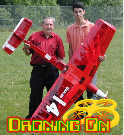
 Not all drones are multirotors – Posing in our title photo are Maynard Hill and Cyrus Abdollahi. Maynard’s plane, TAM5 aka The Spirit of Butts Farm, is the smallest aircraft to make a transatlantic flight (YouTube link). Retracing the path of Alcock and Brown from Newfoundland to Ireland, the 6 pound (dry weight) model made the trip in just under 39 hours. All this happened in 2003, and was the cap on a lifetime of achievements for Hill. These are the types of pursuits that will be banned in the USA if the FAA restrictions go into effect.
Flight Controllers
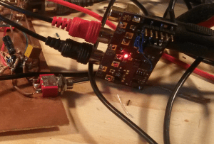
Quite a few of you thought the Naze32 was left out of last column’s flight controller roundup. I hear you loud and clear! I’ll add the Naze to the controllers which will be tested on The Hackaday Testbed. The hard part is finding the darn things! I currently have an Acro Naze32 on its way to Droning On HQ. If I can find a full version, I’ll add that.
PID Controllers Deep Dive
I’ve gotten a few questions on Proportional Integral Derivative (PID) controllers, so it is worth diving in a bit deeper to explain what a PID controller is. PID controllers are often found in process controls managing parameters like temperature, humidity, or product flow rate. The algorithm was initially designed in the late 1800’s as a method of controlling the helm of large naval ships. In fixed wing drones, PID keeps the plane’s wings level and on course. In multicopters, PID loops control heading, but they also provide the stable flight which allows the quadcopter to fly in the first place. A full explanation of PID loops would be beyond the scope of a single article, but let’s try a 10,000 foot explanation.
 P: This is the “Present” parameter. P Has the most influence on the behavior of the aircraft. If the wind blows your quadcopter from level flight into a 30 degree right bank, P is the term which will immediately take action to level the quad out. If the P value is too high, The quadcopter will overshoot level flight and start banking the other way. In fact, way too high a P value can cause a quadcopter to shake as it oscillates or “hunts” for level. Too Low a P value? the quadcopter will be very slow to react, and may never quite reach level flight again.
I: This the “Past” parameter. The I term dampens the overshoot and oscillations of the P term, and avoids the tendency of P to settle above or below the set point. Just like with P, too high an I term can lead to oscillation.
D: This is the “Future” parameter, and has the smallest impact on the behavior of the aircraft. In fact, some flight controllers leave it out entirely. If P and I are approaching a set point too quickly, overshoot is likely to occur. D slows things down before the overshoot happens.
So why do multicopter pilots dread PID tuning? Quite simply, it’s a tedious process. Couple a new pilot and an unproven aircraft with un-tuned PID values, and you have a recipe for frustration – and broken propellers. Things get even more complex when you consider the fact that there are at least 3 sets of PID variables to be tuned – Pitch, Roll, and Yaw. Some flight controllers now support multiple PID values depending on the style of flight. Want your plane or multicopter to fly around like a hotrod? You need a totally different set of PID values than a docile trainer craft. Rolf Bakke (KapteinKUK himself) made a video illustrating how multicopters behave when tuning PID values. You can easily see how a quad can go from “drunk” to “angry bee” with just a few value tweaks. All this is coming together with The Hackaday Testbed, which will help me in posting a few PID tuning videos of my own.
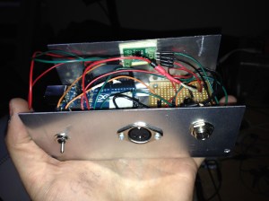
Hackaday Testbed Update
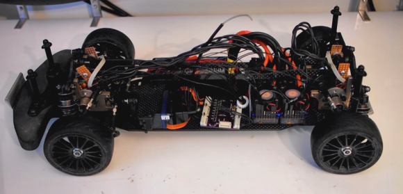
As for the testbed itself, it’s nearly complete! You can follow the progress on my Hackaday Projects Page. Most of the assembly has been relatively straightforward. though of course there are always a few snags. It seems I always forget something when ordering up parts for 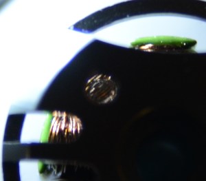 a build. In this case it was 2.5mm banana plugs and motor mounting screws.
The Hobbyking motors attach to the frame with 3mm screws. The problem is that there really is no way to know how long the screws should be until you have the motors, mounting plates and drone frame on hand. I have a bunch of 3mm screws of various lengths, and thankfully there were enough screws of the correct length to mount the motors. Murphy is always at my side, as I accidentally grabbed a screw that was 1mm too long and, you guessed it, screwed right into the windings of the motor. Doh! Thankfully I had spares.
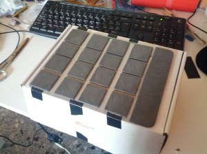
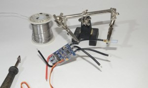 Bullet connectors can be a real pain to solder. There are some jigs out there which help, but I’ve always found myself going back to the old “helping hands” alligator clips. Bullets tend to use lower gauge wire than we’re used to with regular electronics. 14, 12, even 8 gauge wires are used on R/C aircraft. A low power soldering iron with a surface mount tip just won’t cut it. Those irons just doesn’t have the thermal mass to get the connectors up to soldering temperature. This is one of those places where a decent 40 watt or better Weller iron (yes, the kind that plugs right in the wall) can be a godsend. I’m using an Metcal iron here, with a wide flat tip.
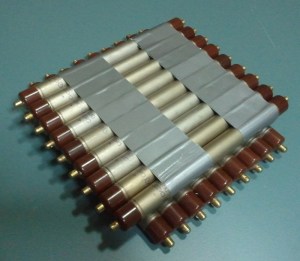
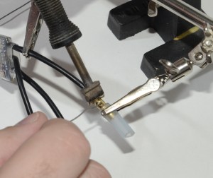 Bare bullet connectors and alligator clips can also create a problem – the metal clips create even more thermal mass. Years back an old-timer showed me a trick to handle this. Slip a piece of silicone R/C plane fuel tubing on the bullet, and then clip the helping hands onto the tube. The tube will act as insulation between the bullet and the clip. Silicone can easily withstand the temperatures of soldering. I’ve also used the silicone tube on the jaws themselves – though eventually the jaws will cut the soft tubing.
That’s about it for this edition Droning on! Until next time, keep ’em flying!
Title photo credit Cyrus Abdollahi.


 Both [Tom’s]

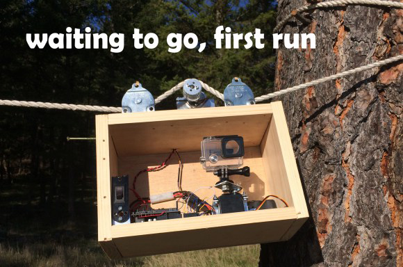 [David Schwarz] whipped up this
 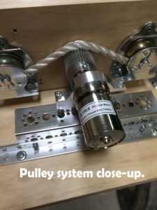 David] built and tested his rig over a weekend. On Monday morning, he gave the rig its first run. The video came out pretty good, but he knew he could get a better shot. That’s when Murphy struck. The motor and controller on his rig decided to give up the ghost. With the contest deadline less than 24 hours away, [David] burned the midnight oil and replaced his motor and controller.


