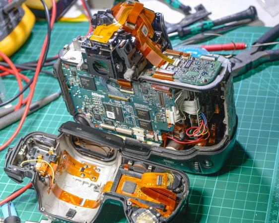
Sinclair ZX Spectrum +2A Slims Down

sinclair

[Carl] got his hands on a dead Sinclair ZX Spectrum +2A. He decided he wasn’t just going to fix it, he was going to improve it! The ZX Spectrum Compact is literally a “sawn-off” Spectrum +2A. [Carl’s] inspiration came from a similar mod at the Old Machinery blog.

Amstrad seems to have had a habit of bolting on additions to their products. In the case of the Spectrum +2A, it was a tape drive. Tapes weren’t a great storage method in the 80’s, and today they’re downright annoying. [Carl] didn’t need the tape interface, as he’s using a DiVide ATA interface.

The modification is rather straight forward. [Carl] broke out the hacksaw and cut the right end cap away from the tape drive. He then cut the entire tape drive away. The motherboard wasn’t safe from the saw treatment either, as the printer interface was cut off. Thankfully there were no components on the printer interface. Apparently [Carl] didn’t short any traces as he went to town with his saw.

With the motherboard modified to fit the abbreviated case, [Carl] was ready to begin reconstruction. He glued the cap onto the sawn-off case with Grip Fill glue, which also served to fill any gaps. Some sanding, priming, and painting later, The ZX Spectrum Compact was finished. This isn’t a perfect mod, as the gap is still slightly visible under the paint – but it’s good enough for [Carl]. Hey, it’s good enough for us, too – we can’t all be [Ben Heck]!


Neo Geo Gets Line Doubled

NeoGeoScan

We love old video games, but we hate the way analog interlaced video looks on our new LCD monitors. [Michael] feels the same way, so he’s created NeoVGA, A Neo Geo Line Doubler in VHDL. Neo Geo, like many classic consoles, didn’t use the full resolution of an analog TV. In NTSC mode, it ran at 320×224 pixels. PAL users got an extra 32 vertical pixels for 320×256 pixels. The system ran with an approximately 15kHz horizontal sync and ~60Hz vertical sync.

This is not exactly a VGA compatible signal, so it would be relegated to composite or S-Video capable displays. The signals looked pretty good on a CRT, but on an LCD, they tend to look crummy. Modern LCDs don’t natively handle interlaced and/or low resolution input signals. The TV’s controller performs the magic of buffering, interpolating, and transforming the input signal to be compatible with the LCD panel. As [Michael] explains, most of these algorithms are optimized for TV video signals with lots of motion. They perform poorly on static high contrast images such as the background of a fighting game. TV controllers also add lag to the signal chain. Not much of a problem when watching movies, but it’s a big problem when you’re trying to pull off that triple hit combo.

Click past the break for more on [Michael’s] creation.

Continue reading “Neo Geo Gets Line Doubled”

Mikey, The Robot That Charges Itself


mikey-the-robot

Mikey is [Mike’s] autonomous robot. Like any good father, he’s given the robot his name. Mikey is an Arduino based robot, which uses a Pixy camera for vision.

[Mike] started with a common 4WD robot platform. He added an Arduino Uno, a motor controller, and a Pixy. The Pixy sends directions to the Arduino via a serial link. Mikey’s original task was driving around and finding frogs on the floor. Since then, [Mike] has found a higher calling for Mikey: self charging.

One of the most basic features of life is eating. In the case of autonomous robots, that means self charging. [Mike] gave Mikey the ability to self charge by training the Pixy to detect a green square. The green square identifies Mikey’s charging station. Probes mounted on 3D printed brackets hold the positive leads while springs on the base of the station make contact with conductive tape on Mikey’s belly. Once the circuit is complete, Mike stops moving and starts charging.

Continue reading “Mikey, The Robot That Charges Itself”

NYC Resistor Gets A PDP-11/34

PDP-11/34 NYCR

[Trammel Hudson] and NYC Resistor have gotten their hands on some old computing iron in the form of a PDP-11/34.  The PDP-11 is a 16 bit minicomputer made by Digital Equipment Corporation (DEC). Various incarnations of the PDP-11 were sold from the 1970’s all the way into the 1990’s. NYC Resistor’s model is has a label dating it to 1983.

The PDP was found in an old storage unit in the Bronx. Moving several racks of equipment across the city is no small feat, but NYC Resistor members have it done it so many times they’ve got it down to a science.

Once power is applied, a stock PDP won’t actually do anything until the boot loader is keyed in from the CPU front panel. Thankfully this particular PDP-11 had its boot instructions printed on a label on the CPU. NYCR’s machine also includes an M9312 “bootstrap / Unibus terminator” board, which allows the machine to boot at the push of a button.

The team connected the racks, terminals, and drives. Carefully following the instructions, they actually got their PDP to boot up! Their next step is to start reading in some of the old tapes that came with the machine. We’re all waiting with bated breath to see what “digitized monkey brains” contains. Once the machine is fully functional, we hope they get it on the internet and load up The Hackaday Retro Edition.

Continue reading “NYC Resistor Gets A PDP-11/34”

A Ring Of Colored Pencils

Colored Pencil Ring

[Peter] proved he has equal parts prowess, patience, and perseverance with this colored pencil ring (imgur link). The ring is made from a cross-section of several colored pencils. The idea seems simple. The build process IS simple. As always though, the devil is in the details.

[Peter] started with a cheap pack of colored pencils. They have to be hexagonal pencils, as round ones won’t work well for this build. [Peter] used two nails to align the  pencils, and medium thickness Cyanoacrylate glue to bond them together. Cyanoacrylate (aka super glue) is a very strong but inflexible bond. We’re curious if a different adhesive might have worked better for this task.

Once the block of glued pencils was dry, [Peter] drilled a hole approximately his ring size. He used a band saw to cut a rough ring blank around the hole, then headed to the wood lathe. He mounted the ring with a jam chuck, which is a piece of wood turned to an interference fit with the workpiece. The problem was that the jam chuck cracked the ring as it was being installed. [Peter] was able to glue the ring back together, and turn it down on his lathe.

Click past the break for more on [Peter’s] ring.

Continue reading “A Ring Of Colored Pencils”

Augmented Reality With An FPGA


bruceinabox


[Julie Wang] has created an augmented reality system on a Field Programmable Gate Array (FPGA). Augmented reality is nothing new – heck, these days even your tablet can do it. [Julie] has taken a slightly different approach though. She’s not using a processor at all. Her entire system, from capture, to image processing, to VGA signal output, is all instantiated in a FPGA.

Using the system is as simple as holding up a green square of cardboard. Viewing the world through an old camcorder, [Julie’s] project detects and tracks the green square. It then adds a 3D image of Cornell’s McGraw Tower on top of the green. The tower moves with the cardboard, appearing to be there. [Julie] injected a bit of humor into the project through the option of substituting the tower for an image of her professor, [Bruce Land].

[Julie] started with an NTSC video signal. The video is captured by a DE2-115 board with an Altera Cyclone IV FPGA. Once the signal was inside the FPGA, [Julie’s] code performs a median filter. A color detector finds an area of green pixels which are passed to a corner follower and corner median filter. The tower or Bruce images are loaded from ROM and overlaid on the video stream, which is then output via VGA.

The amazing part is that there is no microprocessor involved in any of the processing. Logic and state machines control the show. Great work [Julie], we hope [Bruce] gives you an A!

Continue reading “Augmented Reality With An FPGA”

Virtual Reality Gets Real With 3 Kinect Cameras

No, that isn’t a scene from a horror movie up there, it’s [Oliver Kreylos’] avatar in a 3D office environment. If he looks a bit strange, it’s because he’s wearing an Oculus Rift, and his image is being stitched together from 3 Microsoft Kinect cameras.

[Oliver] has created a 3D environment which is incredibly realistic, at least to the wearer. He believes the secret is in the low latency of the entire system. When coupled with a good 3D environment, like the office shown above, the mind is tricked into believing it is really in the room. [Oliver] mentions that he finds himself subconsciously moving to avoid bumping into a table leg that he knows isn’t there. In [Oliver’s] words, “It circumnavigates the uncanny valley“.

Instead of pulling skeleton data from the 3 Kinect cameras, [Oliver] is using video and depth data. He’s stitching and processing this data on an i7 Linux box with an Nvidia Geforce GTX 770 video card. Powerful hardware for sure, but not the cutting edge monster rig one might expect. [Oliver] also documented his software stack. He’s using Vrui VR Toolkit, the Kinect 3D Video Capture Project, and the Collaboration Infrastructure.

We can’t wait to see what [Oliver] does when he gets his hands on the Kinect One (and some good Linux drivers for it).

Continue reading “Virtual Reality Gets Real With 3 Kinect Cameras”