Augmented Reality With An FPGA


bruceinabox


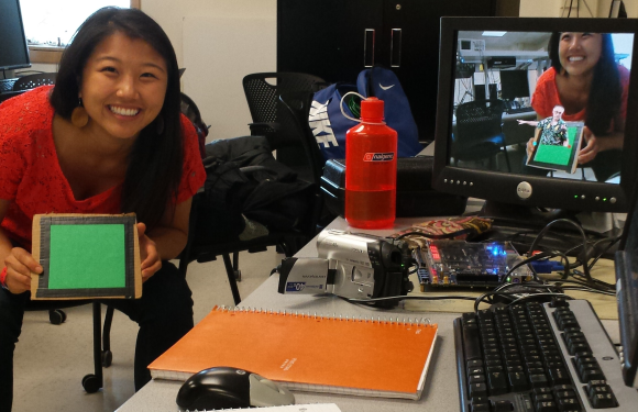
[Julie Wang] has created an augmented reality system on a Field Programmable Gate Array (FPGA). Augmented reality is nothing new – heck, these days even your tablet can do it. [Julie] has taken a slightly different approach though. She’s not using a processor at all. Her entire system, from capture, to image processing, to VGA signal output, is all instantiated in a FPGA.

Using the system is as simple as holding up a green square of cardboard. Viewing the world through an old camcorder, [Julie’s] project detects and tracks the green square. It then adds a 3D image of Cornell’s McGraw Tower on top of the green. The tower moves with the cardboard, appearing to be there. [Julie] injected a bit of humor into the project through the option of substituting the tower for an image of her professor, [Bruce Land].

[Julie] started with an NTSC video signal. The video is captured by a DE2-115 board with an Altera Cyclone IV FPGA. Once the signal was inside the FPGA, [Julie’s] code performs a median filter. A color detector finds an area of green pixels which are passed to a corner follower and corner median filter. The tower or Bruce images are loaded from ROM and overlaid on the video stream, which is then output via VGA.

The amazing part is that there is no microprocessor involved in any of the processing. Logic and state machines control the show. Great work [Julie], we hope [Bruce] gives you an A!
Continue reading “Augmented Reality With An FPGA” →

Virtual Reality Gets Real With 3 Kinect Cameras

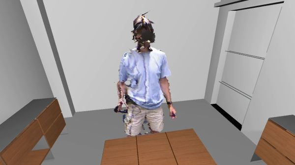
No, that isn’t a scene from a horror movie up there, it’s [Oliver Kreylos’] avatar in a 3D office environment. If he looks a bit strange, it’s because he’s wearing an Oculus Rift, and his image is being stitched together from 3 Microsoft Kinect cameras.

[Oliver] has created a 3D environment which is incredibly realistic, at least to the wearer. He believes the secret is in the low latency of the entire system. When coupled with a good 3D environment, like the office shown above, the mind is tricked into believing it is really in the room. [Oliver] mentions that he finds himself subconsciously moving to avoid bumping into a table leg that he knows isn’t there. In [Oliver’s] words, “It circumnavigates the uncanny valley“.

Instead of pulling skeleton data from the 3 Kinect cameras, [Oliver] is using video and depth data. He’s stitching and processing this data on an i7 Linux box with an Nvidia Geforce GTX 770 video card. Powerful hardware for sure, but not the cutting edge monster rig one might expect. [Oliver] also documented his software stack. He’s using Vrui VR Toolkit, the Kinect 3D Video Capture Project, and the Collaboration Infrastructure.

We can’t wait to see what [Oliver] does when he gets his hands on the Kinect One (and some good Linux drivers for it).

Continue reading “Virtual Reality Gets Real With 3 Kinect Cameras” →

Samsung NX300 Gets Rooted

sammy

[Ge0rg] got himself a fancy new Samsung NX300 mirrorless camera. Many of us would just take some pretty pictures, but not [Ge0rg], he wanted to see what made his camera tick. Instead of busting out the screwdrivers, he started by testing his camera’s security features.

The NX300 is sold as a “smart camera” with NFC and WiFi connectivity. The NFC connectivity turns out to be just an NXP NTAG203 tag embedded somewhere in the camera. This is similar to the NFC tags we gave away at The Gathering in LA. The tag is designed to launch an android app on a well equipped smartphone. The tag can be write-locked, but Samsung didn’t set the lock bit. This means you can reprogram and permanently lock the tag as a link to your favorite website.

[Ge0rg] moved on to the main event, the NX300’s WiFi interface. A port scan revealed the camera is running an unprotected X server and Enlightenment. Let that sink in for a second. The open X server means that an attacker can spoof keystrokes, push images, and point applications to the camera’s screen.

In a second blog post, [Ge0rg] tackled attaining root access on the camera. Based on the information he had already uncovered, [Ge0rg] knew the camera was running Linux. Visiting Samsung’s open source software center to download the open source portions of the NX300 confirmed that. After quite a bit of digging and several red herrings, [Ge0rg] found what he was looking for. The camera would always attempt to run an autoexec.sh from the SD Card’s root folder at boot. [Ge0rg] gave the camera the script it was looking for, and populated it with commands to run BusyBox’s telnet daemon.  That’s all it took – root shell access was his.


[Image via Wikimedia Commons/Danrok]

A Quadcopter From Scratch

Quadcopter

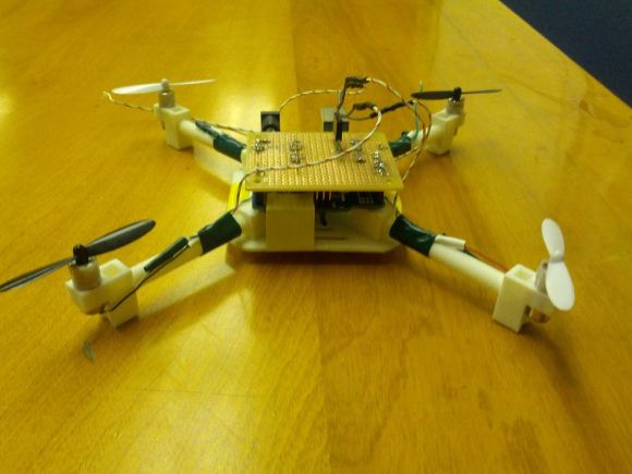
[AwesomeAwesomeness] wanted a low cost quadcopter, so he built one from scratch. Okay, not quite from scratch. [AA’s] cookie mix came in the form of an Arduino Uno and some motors. He started with motors and propellers from a Hubsan X4 quadcopter. Once the power system was specified, [AA] designed a frame, arms, and motor pods in Solidworks. He printed his parts out and had a sweet quadcopter that just needed a brain.

Rather than buy a pre-made control board, [AA] started with an Arduino Uno.  An Arduino alone can’t source enough current to drive the Hubsan motors. To handle this, [AA] added a ULN2003A  Darlington transistor array. The 2003A did work, but [AA] had some glitching issues. We think FETs would do much better in this application, especially when running PWM.

On the control side of things, [AA] added an MPU-6050 Triple Axis Accelerometer and Gyro breakout from SparkFun. The 6050 has 3 gyros and 3 accelerometers in one package. Plenty for a quadcopter.

All this left was the coding. Multicopters generally use Proportional-Integral-Derivative (PID) control loops to maintain stability in the air. [AA] used the Arduino PID library for his quadcopter. He actually created two PID instances – one for pitch and one for roll.

[AA] doesn’t have any videos of his quadcopter in action yet, and we’re guessing this is due in part to weight. Lifting an Uno, a perfboard, and a frame is a tall task for those motors. Going with a one of the many tiny Arduino’s out there would help reduce weight. In addition, [AA] could use a gear system similar to what is used in the Syma X series quadcopters. Stick with it – you’re on the right track!


Quadcopter Built From Recycled Motherboards

A quadcopter built from a motherboard

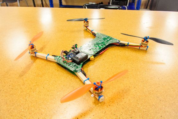
[Eric] has figured out a great way to build quadcopters out of recycled computer motherboards. Multicopters come in all shapes and sizes these days. As we mentioned in the last issue of Droning On, they can be bought or built-in a multitude of materials as well. Drones have been built using materials as varied as wood, PVC pipe, carbon fiber, and aluminum.

One of the more common commercial materials is G10 fiberglass sheet. It’s stiff, strong, and relatively light. Printed circuit boards are generally made of FR-4 fiberglass, G10’s flame resistant cousin. It’s no wonder [Eric] had quadcopters in his eyes when he saw a pile of motherboards being thrown out at his university.

[Eric] used a heat gun and a lot of patience to get all the components off the motherboard. With a bit of care, most of the components can be saved for future hardware hacks. This is one step that’s best performed outside. Hot melting plastics, metals, and resin fumes aren’t the greatest things to inhale.

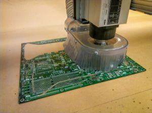
Computer motherboards being cut on a shopbotClean PCBs in hand, [Eric] headed to his local TechShop. He drew his dead cat style frame in SolidWorks and cut it out on a ShopBot. While a high-end CNC cutter is nice, it’s not absolutely necessary. The fiberglass sheets could be cut with a rotary tool or a jigsaw. No matter how you cut it, be sure to wear a mask rated for fiberglass resins and some protective clothing. Fiberglass plate is nasty stuff to cut.

Once the upper and lower frame plates were cut, [Eric] completed his quad frame with some square wooden stock for arms. The final quad is a great flier, and spare parts are easy to source. Nice work on the recycling, [Eric]!

Continue reading “Quadcopter Built From Recycled Motherboards” →

Two Wheeler Is Gyroscope Stabilized

[Jim] loves gyros – not those newfangled MEMS devices, but old-fashioned mechanical gyroscopes. His obsession has pushed him to build this gyro stabilized two wheeler. We love watching hacks come together from simple basic materials and hand tools, with liberal amounts of hot glue to hold everything in place.  That seems to be [Jim’s] philosophy as well.

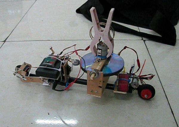
This is actually the fifth incarnation of [Jim’s] design. Along the way he’s learned a few important secrets about mechanical gyro design, such as balancing the motor and gyro assembly to be just a bit top-heavy. [Jim’s] gyro is a stack of CDs directly mounted to the shaft of a brushed speed400 R/C airplane motor. The motor spins the CDs up at breakneck speed – literally. [Jim] mentions that they’ve exploded during some of his early experiments.

The gyroscope is free to move in the fore-aft direction. Side to side balance tilting is on the wheels themselves. The wheels are model airplane wheels, which have a curved tread. No cheating by using flat LEGO wheels in [Jim’s] lab! A potentiometer measures the tilt angle of the gyro. The voltage from the pot is fed into an Arduino Uno which closes the loop by moving a servo mounted counterweight.

The vehicle is controlled with a regular R/C plane radio. A servo steers the front wheel while another DC motor drives the rear wheel. Not only is [Jim’s] creation able to balance on its own, it can even make a U-Turn within a hallway.

Continue reading “Two Wheeler Is Gyroscope Stabilized” →

Dual Port RAM Teaches An Old NES New Tricks

nesDPR

[Andrew] is developing a game for the Nintendo Entertainment System (NES). Emulators are great for this, but [Andy] loves running on the real iron. To help, he’s created a dual port RAM interface for his NES. As the name implies, a dual port RAM is a memory with two separate data and address buses. The Cypress Semiconductor CY7C136 [Andy] used also includes arbitration logic to ensure that both ports don’t attempt to access the same memory cell and cause data corruption. In [Andy’s] case the NES was on one side, oblivious to the new hardware. On the other side of the dual port RAM, [Andy] installed an ATmega164 running his own custom firmware.

The new hardware gives [Andy] a live view of what’s going on in the NES’s memory. He added a live memory view/edit screen similar to the FCEUX emulator. The window runs on a PC while the game itself is running on an NES. [Andy] was even able to add rudimentary break and step features by connecting his circuit to the Non Maskable Interrupt (NMI) line of the NES. By holding the NMI asserted, the ATmega can essentially freeze the game in progress.

[Andy] has even used his circuit to teach the NES some new tricks. By reading the timer and score memory locations on Ice Hockey, he was able to create a scoreboard and goal light. Similar techniques were used to give Contra a muzzle flash light which puts Ambilight systems to shame.

We don’t know what [Andy] is planning next, but we hope it’s a source release so we can start hacking some some games ourselves!

Click past the break to see a couple of [Andy’s] Vine videos.

Continue reading “Dual Port RAM Teaches An Old NES New Tricks” →