[Andreas] has created this tutorial on real-time (RT) tasks in Linux. At first blush that sounds like a rather dry topic, but [Andreas] makes things interesting by giving us some real-world demos using a Raspberry Pi and a stepper motor. Driving a stepper motor requires relatively accurate timing. Attempting to use a desktop operating system for a task like this is generally ill-advised. Accurate timing is best left to a separate microcontroller. This is why we often see the Raspi paired with an Arduino here on Hackaday. The rationale behind this is not often explained.
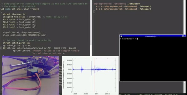
[Andreas] connects a common low-cost 28BYJ-48 geared stepper motor with a ULN2003 driver board to a Raspberry Pi’s GPIO pins. These motors originally saw use moving the louvers of air conditioners. In general, they get the job done, but aren’t exactly high quality. [Andreas] uses a simple program to pulse the pins in the correct order to spin the motor. Using an oscilloscope, a split screen display, and a camera on the stepper motor, [Andreas] walks us through several common timing hazards, and how to avoid them.
The most telling hazard is shown last. While running his stepper program, [Andreas] runs a second program which allocates lots of memory. Eventually, Linux swaps out the stepper program’s memory, causing the stepper motor to stop spinning for a couple of seconds. All is not lost though, as the swapping can be prevented with an mlockall() call.
The take away from this is that Linux is not a hard real-time operating system. With a few tricks and extensions, it can do some soft real-time tasks. The best solution is to either use an operating system designed for real-time operation, or offload real-time operations to a separate controller.
Continue reading “A Tutorial On Using Linux For Real-Time Tasks”

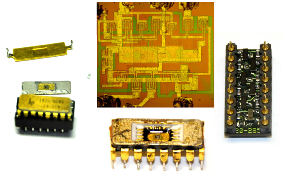 [Matthew] got himself into a real pickle. It all started when he was troubleshooting a broken Hewlett Packard 8007A pulse generator. While trying to desolder one of the integrated circuits, [Matthew] accidentally cracked it. Unfortunately, the chip was a custom HP Pulse shaper IC – not an easy part to source by any means. That broken chip began a 5 year mission: to explore strange new repair methods. To seek out new life for that HP 8007A.