[Jason] always wanted a touchscreen TV remote control. He could have pressed an older Android tablet into service, but he wanted to roll his own system. [Jason] gathered the parts, and is in the process of building his own 7″ touchscreen setup. He started with a 7″ LCD capacitive touchscreen. He ordered his display from buy-display.com, a Far East vendor.
[Jason’s] particular display model comes mounted on a PCB which includes controllers for the display and touchscreen, as well as some memory and glue logic. The LCD controller board has quite a few jumpers to support multiple interfaces and options. While the documentation for the display was decent, [Jason] did find a few errors. After getting in touch with tech support at buy-display, he wrote a simple application which determines which jumpers to set depending on which hardware interfaces are selected from drop down lists.
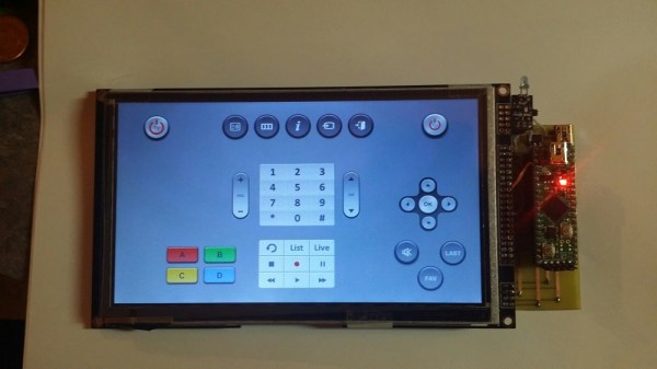
With the LCD sorted, [Jason] still needed a processor. He selected the venerable Microchip PIC32MX series. This decision allowed him to use a Fubarino for the early prototypes, before switching to his own board as the system matured. [Jason] was able to get a simple GUI up and running, with standard remote buttons to control his TV and cable box. Code is on his Github repository.
[Jason’s] most recent work has centered on cutting the cord. He’s switched over from DC power to a 2600 mAh LiPo battery. Click past the break to see [Jason] test out his fully wireless work in progress.
Continue reading “A 7″ Touchscreen TV Remote Control From Scratch”