An Even Larger Array Of Many LEDs And No Ping-Pong balls

Color Led Matrix

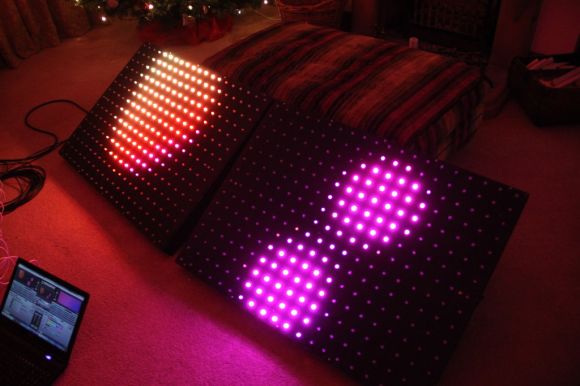
[George] has gone pro with his latest RGB LED panel. We’ve chronicled [George’s] journey toward the elusive land of LED nirvana for a couple of years now. He started with an 8×8 rainbow board of many ping-pong balls. When that wasn’t enough, he upped the ante to a 32×16 array of ping-pong balls. Still not satisfied, [George] has now increased the size to two 20×15 panels, for a total of 600 LEDs. While this is only a modest size increase from the previous incarnation, the major changes here have been in the design and construction of the array.

[George] found himself using his LED panels in some professional settings. The stresses of moving and rigging the panels revealed several design weaknesses. The point to point discrete LED design tended to short, leading to troubleshooting by poking at wires in a dark club. The control code was also a mixed bag of solderlab’s code, [George’s] code, and various scripts. Even the trademark ping-pong ball light diffusers were a problem, as they created a fire hazard. [George] took all the lessons from the first and second LED arrays and started a new design – the MX3. The panel frames were constructed by a professional metal shop. Starting with a square steel tube backbone, and aluminum panel shell was welded into place. The steel tube provides a hardpoint mount for any number of rigging options. The front panels are medium-density fibreboard, treated with a fire-retardant paint.

The electronics have also changed. Gone are the individual RGB LEDs. [George] has switched over to the common WS2812 LED strings. Panel mounted Raspberry Pis control the LED strings. Communication is via Art-Net, an Ethernet implementation of the common DMX512 protocol commonly used in stage lighting. The final result looks great.  We’re impressed with how much [George] has accomplished at such a young age (He was 16 last June).

Continue reading “An Even Larger Array Of Many LEDs And No Ping-Pong balls” →
Ambient Computer Noise Leaks Your Encryption Keys

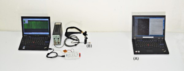
[Daniel, Adi, and Eran], students researchers at Tel Aviv University and the Weizmann Institute of Science have successfully extracted 4096-bit RSA encryption keys using only the sound produced by the target computer. It may sound a bit like magic, but this is a real attack – although it’s practicality may be questionable. The group first described this attack vector at Eurocrypt 2004. The sound used to decode the encryption keys is produced not by the processor itself, but by the processor’s power supply, mainly the capacitors and coils. The target machine in this case runs a copy of GNU Privacy Guard (GnuPG).

During most of their testing, the team used some very high-end audio equipment, including Brüel & Kjær laboratory grade microphones and a parabolic reflector. By directing the microphone at the processor air vents, they were able to extract enough sound to proceed with their attack. [Daniel, Adi, and Eran] started from the source of GnuPG. They worked from there all the way down to the individual opcodes running on the x86 processor in the target PC. As each opcode is run, a sound signature is produced. The signature changes slightly depending on the data the processor is operating on. By using this information, and some very detailed spectral analysis, the team was able to extract encryption keys. The complete technical details of the attack vector are available in their final paper (pdf link).

Once  they had the basic methods down, [Daniel, Adi, and Eran] explored other attack vectors. They were able to extract data using ground fluctuations on the computers chassis. They even were able to use a cell phone to perform the audio attack. Due to the cell phone’s lower quality microphone, a much longer (on the order of several hours) time is needed to extract the necessary data.

Thankfully [Daniel, Adi, and Eran] are white hat hackers, and sent their data to the GnuPG team. Several countermeasures to this attack are already included in the current version of GnuPG.

Shopping Trolley Is Wired For Camp

[James] needed some cool transportation for the upcoming Easter Camp in New Zealand, so he created a custom motorized shopping trolley that is sure to turn heads. The base of this project is a standard mobility scooter, which conveniently has a modular design. All of the electronics have connectors for quick service and the entire rear axle and motor assembly pop off with the pull of a lever.

[James] had to do a bit of welding and chassis rework to achieve his goal of mounting a shopping cart top to the scooter’s frame. Once finished, though, the setup looked great. It was actually comfortable to sit in, as [James] made a cutout for the driver’s feet to pass through. The real fun came with the electronics. The trolley is the most wired mobility scooter mod we’ve ever seen. Most of the electronics are contained in a project box under the seat, with several Arduinos that control the various systems: interfacing with the original scooter electronics, a GPS receiver, and a GSM radio. [James] also went as far as to add RGB LED headlights, a horn, and a multi-tone siren from Jaycar.

Driving the trolley is simple. An arcade joystick selects the speed, and the scooter’s standard hand controls are used for forward, reverse, and steering. One of the more interesting mods [James] made was a custom Windows app to control the trolley via a USB radio module. The entire system can be secured, with the security code stored in NVRAM to prevent a power cycle from unlocking the system. [James] can even command the trolley to go forward or reverse from his touch screen. We’d love to see him add a steering servo to make it a completely remote-controlled solution, though this step would require some sort of clutch for manual control.

The final design works very well.  [James] may not win any drag races by keeping scooter’s original speed controls and associated electronics, but he did extend the range with larger batteries, so we’re sure the trolley will be a hit all over the camp. Similar projects have been built using the base of an electric wheelchair. If you have one that you want to control without invasive changes to the hardware, check out this accessibility hack which interfaces using a connector.

Continue reading “Shopping Trolley Is Wired For Camp” →

Attacknid Becomes Laser Death Drone

Laser Drone

[styroPyro] liked his Attacknid, but decided it needed just a bit more blue death ray laser. We’ve seen [styroPyro’s] high-powered laser hacks before, but this time he’s taken to hacking one of [Jaimie Mantzel’s] Attacknid robots. According to one of the top comments on [styroPyro’s] video—a comment by Attacknid inventor [Jaimie] himself—the robots were meant to be hacked, and [Jamie] is ecstatic.

[styropyro] removed the disk shooter from his Attacknid and used the fire control circuit to activate a 2 watt blue laser. A low powered, red laser pointer serves as a laser sight, allowing you to aim at your target before unleashing the beefy blue laser. As the video shows, 2 watts is a heck of a lot of power. The Attacknid easily pops balloons and sets fire to flash paper. As usual, we urge you to use caution when handling 2 watt lasers, which fall under Class 4: aka the most dangerous class of lasers. Goggles, skin protection, and safety interlocks are the order of the day. [styroPyro] has been working with high power lasers for a few years, and seems to know what he’s doing. That said, we’ll leave the burning lasers to the professionals.

Continue reading “Attacknid Becomes Laser Death Drone” →

Build An In Line Network Bandwidth Monitor

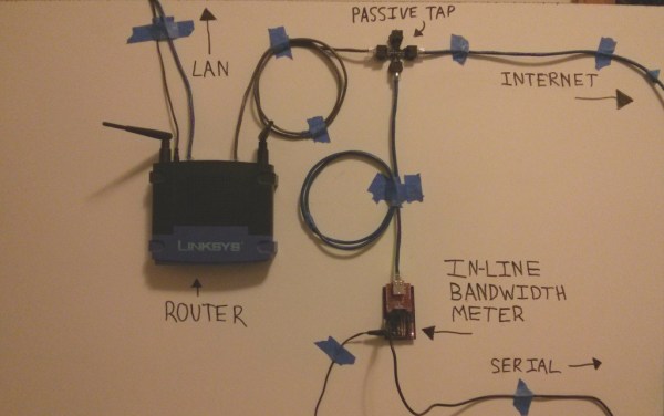
[Kurt] likes to know what’s going on with his network. He already uses bandwidth checking software on his DD-WRT capable router, but he wanted a second opinion. So he built his own network monitor. [Kurt] started by building a passive Ethernet tap. He then needed a network interface chip that would serve his purposes. The common Wiznet chips used with Arduinos didn’t allow enough manipulation of raw packet data, so he switched to a Microchip ENC624J600 (PDF). The Microchip controller allowed him to count the bytes in the raw Ethernet packets.

With the Ethernet interface complete, [Kurt] turned his attention to a microcontroller to run the show. He started with an Arduino, but the lack of debugging quickly sent him to an Atmega128 in Atmel Studio. After getting the basic circuit working, [Kurt] switched over to a PIC24F chip. With data finally coming out of the circuit, he was able to tell that his original back-of-the-napkin calculations for bandwidth were wrong. [Kurt] created a PCB to hold the microcontroller, then wrote a Python program to plot the data output from his circuit. The bandwidth plot matched up well with the plot from DD-WRT. Now he just needs a giant LED matrix to show off his current network stats!

Digital Electric Meter Monitor Goes Old School

powerMeter

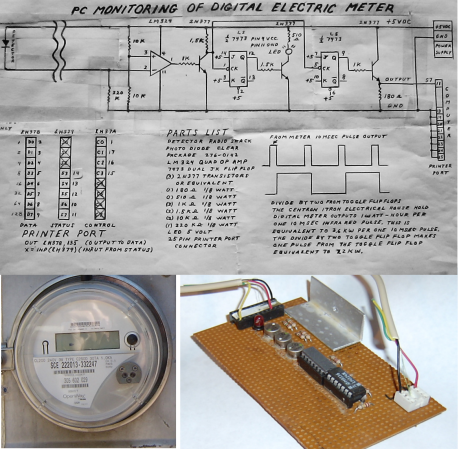
[Sal] sent us his digital electric meter monitor, which immediately made us nostalgic for some of Forrest Mims’ books. Sal’s schematic and circuit description are similar to Forrest’s style, and we mean that as a compliment. Even in today’s world of CAD and EDS packages, sketching out a circuit by hand is sometimes both easier and faster. The schematic isn’t the only classic aspect of [Sal’s] design. He’s collecting data using a parallel port on an unused PC: in this case, a Toshiba Libretto running Windows 95. Before cheap flash-based microcontrollers and dev boards were available, the PC parallel port was the go-to hardware hacking interface for many of us. Plenty of the software running those old hacks was written in basic, and [Sal’s] meter is no exception. His software runs on Microsoft QBasic, which shipped with Windows 95.

The circuit takes advantage of the digital meter’s output: a 10 ms pulse for every 1 Wh of energy used. An IR photo detector from RadioShack detects the meter pulses, which are amplified by an LM324 Op Amp. An NPN transistor then shifts the output to send it to two 74LS73 JK flip flops. The first flip flop uses a transistor to drive an LED for visual output. The second JK flip flop sends the data to the PC. The flip flop has the effect of dividing the number of meter pulses by two, creating a much longer toggled signal that a PC can better detect.

Although using an AVR or PIC would consume less power, [Sal’s] setup has already more than paid for its power usage. By monitoring and adapting his electrical usage, [Sal] is saving $20 a month on his electric bill. We’ve included [Sal’s] circuit diagram and source code after the break (apologies to our readers on RSS).

Continue reading “Digital Electric Meter Monitor Goes Old School” →

Over Engineered Kegerator Is Glorious

keger

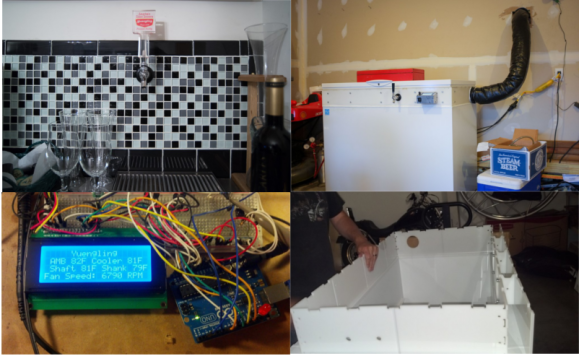
When [Joey] decided to build a kegerator, he didn’t skimp. No commercial unit or simple kit would do. [Joey] wanted complete temperature monitoring, with a tap on the kegerator itself and a cooled tap remotely mounted at his bar. He started with a box freezer, which was a bit short for his purposes. Not a problem, as [Joey] cut an extended collar for the freezer from HDPE on his shopbot. The new collar gives mounting points for the beer lines, gas lines, as well as all the electronics.

Temperature control is handled by a commercial controller, however temperature monitoring is another thing altogether. An Arduino sits in a custom aluminum case on the outside of the kegerator. The Arduino reports temperature, beer type and also controls the cooling system for the beer lines. The cooling system alone is incredible. [Joey] designed everything in CAD and cut the parts out on his shopbot. Two fans sit in an aluminum air box. One fan is used to push cold air out from the freezer around the beer line. A second fan pulls air back in, keeping the kegerator/line/tap air system a (relatively) closed loop. The entire line set is insulated with 2″ fiberglass flex duct.

Temperature data and trend graphs can be monitored on the web, and [Joey] is using a Raspberry Pi to create a wall mounted status screen for his bar room. We love this build! [Joey] we’d buy you a beer, but it seems like you’ve got that covered already!