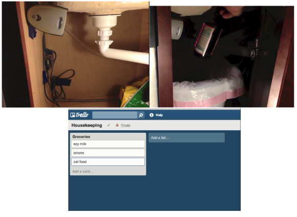
Hack Your Stove In The Name Of Homebrewing

stovehack

[Tim] is a homebrewer. Temperature profiling during the mashing process is apparently even more critical than the temperature curve of a solder reflow oven. His stove just wasn’t giving him the level of control he needed, so [Tim] added a PID temperature controller to his stove. Electric stoves generally use an “infinite switch” to control their burners. Infinite switches are little more than a resistor and a bimetallic strip in a single package. Not very good for accurate temperature control. The tricky part of this hack was to make it reversible and to have little visual impact on the stove. A stove top with wires hanging out would not only be dangerous electrically, it would also create a hazardous situation between [Tim] and his wife.

[Tim’s] brewpot only fit on the stove’s largest burner, so that was the only one that needed PID control. To keep things simple, he kept the commercial PID controller outside the stove’s enclosure. Inside the stove, [Tim] added a solid state relay. The relay is mounted to a metal plate, which screws to the back of the stove. The relay control lines run to an audio jack on the left side of the stove. Everything can be bypassed with a switch hidden on the right side of the stove. In normal operation, the switch is in “bypass” mode, and the stove works as it always has. When mashing time comes along, [Tim] flips the switch and plugs the jack into his PID controller. The temperature sensor goes into the brewpot itself, so no stove modification was needed there.

The end result is a very clean install that both [Tim] and his wife can enjoy.  Save a few bottles for us, [Tim]!

Home Theater For One Shakes Souls, Removes Fillings

hmmmm

Sometimes an earth-shaking home theater setup just won’t do. A speaker enclosure can only fill the average sized room with so much sound. [Kevin Bastyr] has figured out a way around this. Do away with the room, and build the home theater INSIDE the speaker enclosure! [Kevin’s] creation is called Humorously Maniacal Milwaukee Makerspace Multimedia Machine, (or HMMMMMM for short). As the name implies, HMMMMMM was created at the Milwaukee Makerspace. The HMMMMMM reminds us a bit of the sensory deprivation chambers which were so popular in the 70’s. HMMMMMM’s purpose in life however, is anything but deprivation. The user (victim?) climbs through a 27” hatch and settles into a reclining position. An LCD display is mounted a comfortable distance away from the users eyes. Then movie (or brainwashing program) begins.

The sound system is what sets the HMMMMMM apart. The HMMMMMM utilises a 5.16 surround sound system. That’s 5 speakers and 16 10″ high efficiency subwoofers. We’re not sure if it would be better to call it a sound system, or a full-out frontal assault on the senses. We’re not kidding when we say senses as well. Bass this loud can be felt as much as it is heard. The HMMMMMM is has been measured at 148.6dB at 40Hz. That’s well into the hearing damage range. To be safe, HMMMMMM users must wear double hearing protection: foam earplugs and earmuffs.

[Kevin’s] graphs aren’t all smoke and mirrors either – he’s an audio engineer by trade, and made his measurements with a laboratory grade 1/2″ Bruel and Kjaer microphone. Sound pressure level testing isn’t without its dangers. During testing the 2050 watt amplifier powering HMMMMMM encountered a fan failure. The amp’s circuit board ended up scorched black with delaminated traces. The HMMMMMM however was none the worse for wear. Future plans for the HMMMMMM include RGB LEDs that flash to the beat, and a smoke machine to create that extra atmosphere when the escape hatch is opened.

Simple 10 Watt LED Driver Is Hot Stuff

[Peter] needed to drive a high power LED for his microscope. Rather than pick up a commercial LED driver, he built a simple constant current LED driver and fan control. We’ve featured [Peter’s] pumpkin candle LED work here on Hackaday in the past. Today he’s moving on to higher power LEDs. A 10 watt LED would be a good replacement light source for an old halogen/fiber optic ring light setup. [Peter] started with his old standby – an 8 pin Microchip PIC. In this case, a PIC12F1501. A PIC alone won’t handle a 10 watt LED, so he utilized a CAT4101 constant current LED driver from ON Semi. The PIC performs three tasks in this circuit. It handles user input from two buttons, generates a PWM signal to the LED driver, and generates a PWM signal for a cooling fan.

Control is simple: Press both buttons and the LED comes on full bright. Press the “up” button, and the LED can be stepped up from 10% to 100% in 10 steps.  The “down” button drops the LED power back down. [Peter] even had a spare pin. He’s currently using it as an LED on/off confirmation, though we’d probably use it with a 1wire temperature sensor as a backup to thermal protection built into the CAT4101. It may be overkill, but we’d also move the buttons away from that 7805 linear regulator. Being that this circuit will be used with a microscope, it may eventually be operated by touch alone. It would be a bit surprising to try to press a button and end up with a burnt fingertip!

Continue reading “Simple 10 Watt LED Driver Is Hot Stuff”

A POV Spinner Display With Arduino

pov-display

[Martin2250] has been working on a spinning disc style POV display. He’s posted his progress up on reddit. This hack is a great example of using what you have at your disposal. [Martin2250] is using an IR LED and photodiode to determine the rotational speed of the disc. He tried using the Arduino micros() function to delay between the photodiode pulse and turning on his LEDs. As [Martin2250] found out, micros() isn’t quite accurate enough for this purpose.  He’s since switched over to using the AVR’s native timers, and is getting much better results.

The disc in this build is actually a CD. [Martin2250] sanded away the label, then masked out his digits. He “painted” the CD with a black marker. Peeling off the tape revealed his stylized digits. Cardboard, hot glue, and visible LEDs were used to create four light boxes for the digits. The disc can display any four digits at once – perfect for a POV clock. We love the use of on-hand materials in this hack – bits of hard and balsa wood, liberal use of hot glue, and of course cardboard. The only thing missing in our eyes is some duct tape!

[Charles] Tears Into A Ford Fusion Battery

Any time we hear from [Charles Z. Guan], we know it’s going to be a good feature. When he’s linking us to a blog post with phrases like “If you touch the wrong spots, you will commit suicide instantly”, we know it will be a really good feature. [Charles] is no stranger to Hackaday – we’ve featured his GoKarts, Quadcopters, and scooters before. He was even generous enough to let a couple of Hackaday writers test drive ChibiKart around Maker Faire New York last year.

This time around, [Charles] is working on a power system for chibi-Mikuvan, his proposed entry of the Power Racing Series. He’s decided to go with a used battery from a hybrid vehicle. As these vehicles get older, the batteries are finally becoming available on the used market. [Charles] was able to pick up a 2010 Ford Fusion NiMh battery for only $300. These are not small batteries. At 20” wide by 48” long, and weighing in at 150 pounds, you’ll need 2 or 3 people to move one. They also pack quite a punch: 2.1kWh at 275V. It can’t be understated, taking apart batteries such as these gives access to un-fused lethal voltages. Electrocution, arcs, vaporized metal, fire, and worse are all possibilities. If you do decide to work with an EV or hybrid battery, don’t say we (and [Charles]) didn’t warn you.

As [Charles] began taking apart the battery, he found it was one of the most well thought out designs he’d ever seen. From the battery management computers to the hydrogen filled contactors, to the cooling fan controller, everything was easy to work on. The trick to disassembly was to pull the last module out first. Since all the modules are wired in series, removing the last module effectively splits the pack in half, making it much safer to work on. The battery itself is comprised of 28 modules. Each module contains two 4.8V strings of “D” cell sized NiMh batteries. The battery’s capacity rating is 8000 mAh, and [Charles] found they still took a full charge. Since he doesn’t need the pack just yet, [Charles] removed the final bus bars, rendering it relatively safe. Now that he has a power source, we’re waiting to see [Charles’] next stop on the road to chibi-Mikuvan.

Recreate A PCB With A Scanner And Inkscape

turnsig

[John] has managed to replace a broken turn signal PCB by scanning it and converting to Gerber format. [John] purchased a Triumph Spitfire with toggle switch wired up for turn signal control. The “official” replacement part worked better than the toggle switch, but it didn’t cancel after turning. He was able to get the original switch, only to find it had a hole completely burned through the phenolic board. This isn’t completely surprising, as Triumph used a Lucas Industries electrical system. As anyone who has owned a car with a Lucas “prince of darkness” electrical system will tell you, Lucas systems were not known for quality. A quick Google search brings up plenty of pages attesting to this.

Phenolic resin/paper was a common early PCB material.  The FR-4 fiberglass boards most commonly used today could be considered descendants of FR-1 and FR-2 phenolic. (The FR in this case stands for Fiber Reinforced). The standardization worked in [John’s] favor, as his burned board was 31 mils thick, which is still a standard PCB thickness. Re-creating an odd sized board such as this isn’t a hard job. It would however mean spending quite a bit of time with a ruler and a caliper. Rather than spend all that time measuring and re-drawing, [John] scanned his PCB on a flatbed scanner. He used graph paper as a background to verify the image wasn’t being stretched or skewed.

[John] brought his scan into inkscape, and traced both the outline and copper areas. The outline and copper had to be exported as two separate files, so he added corner marks outside the board outline as fiducials.  He then used pstoedit to convert inkscape’s eps output files to gEDA pcb format. The two files were rejoined in gEDA. From there [John] exported a Gerber, and ran it on his home PCB milling machine.  The results look good. [John] plans to make another revision of the board from a professional PCB house with vias to hold the copper to the substrate.

BITX, A Return To Hackers’ Paradise

bitx

[Bill Meara] has finished up his radio. It both looks and sounds great. It was only a few weeks ago that [Bill] posted a guest rant here on Hackaday. The Radio he mentioned building in the rant is now complete. The transceiver itself is a BITX, a 14MHz Single Sideband (SSB) radio designed by Ashhar Farhan VU2ESE. Ashhar designed the BITX as a cheap to build, and easy to tune up transceiver for radio amateurs in India.

By utilizing parts easily sourced from scrapped TV sets, the BITX can be built for less than 300 Indian Rupee – or about $4.70 USD. In [Bill]’s own words, “Five bucks and some sweat equity gets you a device capable of worldwide communication.” He’s not kidding either. [Bill’s] first QSO was with a ham in the Azores Islands of Portugal.

[Bill] built his radio using the “Manhattan” building style, which we’ve seen before. Manhattan style uses rectangular pads glued down onto a copper ground plane. It makes for a more flexible design than regular old dead bug style building. Looking at all those components may be a bit daunting at first, but plenty of support is available. [Bill] has an 18 part build log on the soldersmoke website. There also is an active yahoo group dedicated to the BITX.