There are times when tiny displays no longer cut it. Whether you want to build a tablet or reuse some laptop displays, you will eventually deal with LVDS and eDP displays. To be more exact, these are displays that want you to use either LVDS or eDP signaling to send a picture.
Of the two, LVDS is the older standard for connecting displays, and eDP is the newer one. In fact, eDP has mostly replaced LVDS for things like laptop and tablet displays. Nevertheless, you will still encounter both of these in the wild, so let’s start with LVDS.
The name “LVDS” actually comes from the LVDS signaling standard (Low-Voltage Differential Signaling), which is a fairly generic data transfer standard over differential pairs, just like RS485. Using LVDS signaling for embedded display purposes is covered by a separate standard called FPD-Link, and when people say “LVDS”, what they’re actually talking about is FPD-Link. In this article, I will also use LVDS while actually talking about FPD-Link. Barely anyone uses FPD-Link except some datasheets, and I’ll use “LVDS” because that’s what people actually use. It’s just that you deserve to know the distinction so that you’re not confused when someone mentions LVDS when talking about, say, industrial machinery.
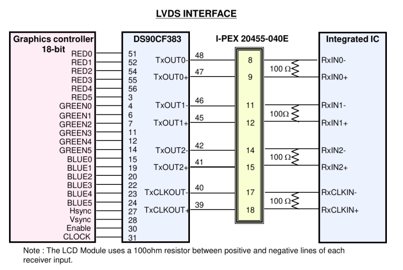
Both LVDS and eDP run at pretty high frequencies – they’re commonly used for color displays with pretty large resolutions, so speed can no longer be a constraint. eDP, as a successor technology, is a fair bit more capable, but LVDS doesn’t pull punches either – if you want to make a 1024 x 768 color LCD panel work, you will use LVDS, sometimes parallel RGB – at this point, SPI just won’t cut it. There’s a lot of overlap – and that’s because LVDS is basically parallel RGB, but serialized and put onto diffpairs. Let me show you how that happened, and why it’s cool.
Continue reading “Displays We Love Hacking: LVDS And EDP” →


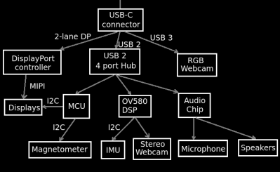 Have you ever wanted to learn how AR glasses and similar devices work, what’s their internal structure, which ones are designed well and which ones maybe not so much? These two posts have concise explanations, more than plenty of diagrams, six case studies of different pairs of AR glasses on the market, each pair demonstrated by our hacker’s canine assistant.