MicroPython Learns A New Trick – ISP For AVRs

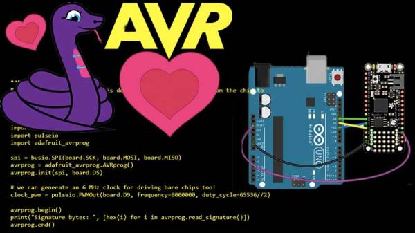
One of the reasons why the Arduino became so popular was the ability to program it with ease. It meant the end of big parallel programmers that would cost an arm and a leg. The latest installment of CircuitPython from [Lady Ada] and the team over at Adafruit is a library for programming AVR microcontrollers without a dedicated PC.

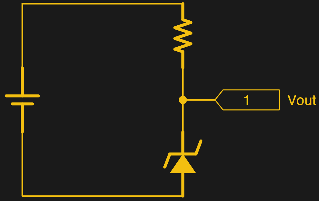
For the uninitiated, in-system programming or ISP for AVR controllers employ the SPI bus to write the compiled binary to the flash memory of the controller. The discount on the number of pins used itself is a benefit though getting the timings right was a bit tricky in the good old days. Most dedicated ISPs handle this nicely, though they are normally slaves to a host PC where an ‘upload’ button initiates the process.

With CircuitPython (a derivative of MicroPython), programming microcontrollers does not require going through the code-compile-flash cycle. It can be run on a number of processors, however, AVRs are not among them so this neat little library offers the next best thing. Wire-up an Atmega328P or ATmega2560 to a board like the ESP8266 that does run CircuitPython, and you can write firmware on the fly.

There is a complete tutorial on the subject thanks to [Phillip Torrone] and [Lady Ada] which includes some demo files for testing out the functionality. This opens up a lot of possibilities where OTA firmware updates for an AVR co-processor. We expect to see some keychain AVR programmers in the near future taking a hint from the ESP8266 based Two-Factor Authentication featured previously.

Measuring HF Signal Speeds In A DIY Coaxial Collinear Antenna

Air Traffic Controllers use Automatic Dependent Surveillance-Broadcast (ADS-B) as an alternative to secondary radar to track aircraft. The ADS-B is transmitted by the aircraft and contains information such as GPS position, pressure, altitude, and callsign among other things at a 1090 MHz frequency, which can be decoded using any of a number of software tools.

[Mike Field] lives near an airport, and decided he wanted to peek into the tracking signals for fun. He turned to an RTL-based TV Dongle. Since the stock antenna was not cutting it, he decided to make one specifically for the 1090 MHz signal. His design is based on Coaxial Collinear Antenna for ADS-B Receiver by [Dusan Balara] which uses pieces of the coaxial cable cut to the right length. There are a number of calculations involved in determining the size of the cable, however, the hack in this design is the way he uses a USB based oscilloscope to measure the speed of RF waves inside the line in question.

We reached out to [Mike], and this is what he had to say. The idea is to use a cable of half the size of the wavelength which is calculated as

lambda = c/f

For the best reception, the sections of coax need to be half a wavelength long – but the wavelength of the signal inside the coax, which is shorter than the wavelength in free space. As this was a generic cable he had no idea of the dielectric that separates the core from the shield, so the ‘velocity factor’ could be anything depending on the exact composition.

To determine the speed of the signal in the cable, his approach omits the more expensive equipment. A length of coax acts as a stub – any energy that is sent into the cable reaches the far end of the transmission line and is then reflected back to the source. When the cable is 1/4th of the wavelength long, the reflected signal arrives back at the start of the signal 180 degrees out of phase – in a perfect world it would completely null out the input signal. Continue reading “Measuring HF Signal Speeds In A DIY Coaxial Collinear Antenna”

A Few Caps For A Faster Multimeter

We just love it when someone takes apart a bench instrument. There is something about voiding a warranty and then making modifications that hits the spot and in a series of simple modifications, [Jack Zimmermann] dives into the guts if an Aneng AN8008.

The multimeter in question, the AN8008, is a low-cost true-RMS instrument that takes a bit longer to settle on the correct voltage reading than [Jack] would have liked. While poking around, he found that the DC rail inside the meter was host to noise spikes. He theorized that these were being coupled back from an element and proceeded to verify the decoupling arrangement.

The first step was to replace a Rubycon 100 uF capacitor with a Panasonic FM 100 µF which has an ESR of 0.4 Ohms, an improvement on the 1.4 Ohms of stock capacitor. Next came the addition of 0.1 µF, 1 µF and a 10 µF 0805 capacitors and finally a huge 1000 uF 10 V capacity which helped cut down the noise from 30 mV p-p to 3.6 mV p-p. And finally he added decoupling capacitors to the voltage reference chip in accordance with the manufacturer’s datasheet.

These small modifications improved the settling time as well as the stability of the measurements. [Jack] verifies the accuracy against a voltage reference and a bench meter which is good news considering the calibration certificate went out the door anyway.

This is one of the many DMM hacks we have covered in the past such as the Fluke 12E+ hack that enables hidden features though there may be other models out there with possible upgrades.

The Web Clock You Can Control Over A LAN

Not every project is meant to solve a new problem. Some projects can be an extension of an existing solution just to flex the geek muscles. One such project by [limbo] is the Web Clock 2.0 which is an internet-connected clock.

Yes, it uses a WEMOS D1 mini which is equipped with an ESP-12F (ESP8266) and yes, it uses an LCD with an I2C module to interface the two. The system works by connecting to the Google servers to get GMT and then offsets it to calculate the local time. It also has the hourly nagging chime to let you know that another precious hour of your life has gone and you need to set it up.

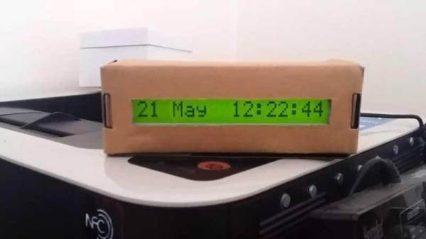
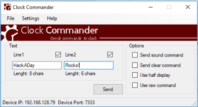
What [limbo] adds to the conventional functionality is a LAN application to send custom messages to the LCD. The software is called ‘Clock Commander’ and can be downloaded as a Windows binary through the source code is unavailable for now. Simply point it to the correct IP address and you can then send it commands to display stuff as well as control the sound. The project comes with Lua scripts and instruction how to DIY.

We imagine this can be used to create a custom geeky table clock or hack a digital coo-coo clock to drive your co-workers crazy at the press of a button. For those who are looking for something with lasers, check out the Laser Pointer Clock for a slightly more challenging build. Continue reading “The Web Clock You Can Control Over A LAN”

A Lesson On Zener Regulators

For the longest time, Zener diode regulators have been one of those circuits that have been widely shared and highly misunderstood. First timers have tried to use it to power up their experiments and wondered why things did not go as planned. [James Lewis] has put up a worth tutorial on the subject titled, “Zener Diode makes for a Lousy Regulator”  that clarifies the misconceptions behind using the device.

[James Lewis] does an experiment with a regulator circuit with an ESP8266 after a short introduction to Zener diodes themselves. For the uninitiated, the Zener diode can operate in the reverse bias safely and can do so at a particular voltage. This allows for the voltage across the device to be a fixed value.

This, however, depends on the current flowing through the circuit which in turn relies on the load. The circuit will work as expected for loads the draw a small amount of current. This makes it suitable for generating reference voltages for microcontrollers and such.

To make a Zener into a “proper” voltage regulator, you just need to buffer the output with an amplifier of some kind. A single transistor is the bare minimum, but actually can work pretty well. You might also add a capacitor in parallel with the Zener to smooth out some of its noise.

Zener diodes are wonderful little devices and write-ups like these are indispensable for beginners and should be shared more often like the Zener and Schottky Tutorial and Diodes as a Switch.


3D Printed Lamp Even Prints The Nuts And Bolts

The first print to come off a shiny new 3D printer is usually a toy widget of some sort that will forever sit at your desk without purpose. The alternative is a practical project that is custom and personal like this 3D Printed Articulating Lamp. [IgorF2] shares his design for this wall mounted device which was created using Fusion 360.

The complete design consists of eight parts which includes the arms, nuts, and bolts, as well as the wall mount, each of which can be printed individually. These come together to form a structure that can be attached to a wall or your work bench. Though [IgorF2] has provided arm pieces of length 100 mm, 140 mm and 200 mm, you can mix and match to create a much larger project. The files are available for download from Thingiverse for your making pleasure.

We think this can be a great basic structure for someone looking at custom wall mounted projects. The lamp mount can be easily supplemented by a Raspberry Pi and Camera holder if you feel like live streaming your bench. Alternatively, it may be customized to become a motion detecting lamp just for fun. We hope to see some good use come of it in the future.

3D Printing On The Subway; Or Anywhere Else!

3D-Printed wearable electronics are on the rise, however our own [Naomi Wu] flipped it around and made a wearable 3D printer which not only is portable but also manufactures on the move!

The project starts with a baby carrier that was locally purchased, and the extra fat was trimmed off leaving behind only the primary harness and square frame. This square frame is left intact to provide stability to the mounted printer as well as some level of comfort to the wearer. [Naomi] then drills a number of new holes in the delta printer in question, of which fortunately the top is made of plastic. Using swivel screws and long screws, the upper part connects with the harness. The receptacle clamp for the upper part is 3D-printed as well, and provides a modular rigid fixture for the machine.

The lower part also uses a 3D-printed triangular base that has a slot for the carrier frame which attaches with the bottom part of the delta using screws. The project is powered via two 3 Ah batteries that are kept in place behind the printer using custom clamps made with PLA. The whole project works on the move, as demonstrated by [Naomi] in the video below.

From dissecting the baby carrier to puncturing holes in a harness using a screwdriver heated by a blow torch, this project has a lot of DIY in it. For those looking for a more productive motorised wearable, check out Adding Haptic Feedback For The Disabled. Continue reading “3D Printing On The Subway; Or Anywhere Else!”