Artist Inadvertently Builds Hodoscope

A Hodoscope is an instrument used to determine the trajectory of charged particles. It’s built out of a three-dimensional matrix of particle detectors – either PIN diodes or Geiger tubes – arranged in such a way that particles can be traced along coincident detectors, revealing their trajectory.

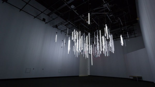
This is not a hodoscope. It’s a chandelier. This chandelier is made of 92 individual Geiger tubes, each connected to a single LED fixture and a speaker. When a charged particle flies through the room and hits a Geiger tube, the light fixture lights up, a ‘click’ plays on the speaker, and the entire room is enveloped in light for a short moment in time. If, however, that charged particle continues on to another Geiger tube, the trajectory of the particle can be deduced.

The purpose of the installation – beside just being art or something – is to show the viewer sources of radiation and normal levels of radioactivity due to terrestrial and cosmic sources. Of course the spacing of these detectors is rather large – it’s made to fit in a gallery – and there is no connection between the detectors, making a coincident circuit impossible. If you want a real hodoscope, here you go.

This installation can be seen at the Burchfield Penney Art Center in Buffalo, NY through April 12. If you’re in the area, go there and eat a banana. Video below. Thanks [David] for the tip.

Continue reading “Artist Inadvertently Builds Hodoscope”

Revive The Demoscene With A LayerOne Demoscene Board

Demos, the demoscene, and all the other offshoots of computer arts had their beginning as intros for cracked Apple II, Speccy, and Commodore 64 games. Give it a few years, and these simple splash screens would evolve into a technological audio-visual experience. This is the birth of the demoscene, where groups of programmers would compete to create the best demonstration of computer graphics and audio.

For one reason or another, this demoscene was mostly confined to Europe; even today, 30 years after the Commodore 64, the North American demoscene is just a fraction of the size of the European scene. A very cool guy named [Arko] would like to change that, and to that end he built the LayerOne Demoscene Board.

If there is a problem with the modern demo scene, it’s that the hardware that’s usually used – C64s, Ataris, Spectrums, and Amigas – are old, somewhat rare, and dying. There’s also the fact that artists have been working on these old machines for decades now, and every single ounce of processing power and software trickery has been squeezed out of these CPUs. [Arko]’s board is a ground-up redesign of what a board that plays demos should be. There’s only one chip on the board – a PIC24F with three graphics acceleration units, color lookup tables, and the ability to output 16-bit VGA video up to 640×480 with 8-bit audio.

The first official competition with the LayerOne Demoscene Board will be at the 2015 LayerOne conference in Monrovia, CA on May 23. There are a few categories, including 4k and 64k JavaScript, Raspberry Pi, the LayerOne board, and a ‘Wild’ category. If you want to take a processor out of a toaster and make a demo, this is the category you’ll be entering. Of course Hackaday will be there, and we’ll be recording all the demos.

Below are a few examples of what the LayerOne Demoscene board can do, and you can also see a talk [Arko] gave at the Hackaday 10th anniversary party here. You can buy the Layerone Demoscene Board on the Hackaday Store

Continue reading “Revive The Demoscene With A LayerOne Demoscene Board”

Using Cheap Displays With The Raspberry Pi

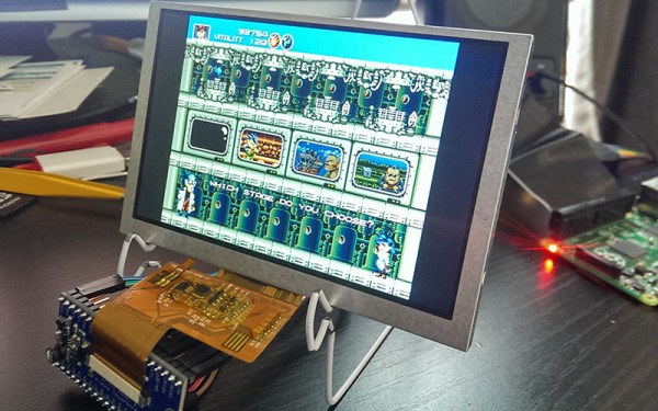
The Raspberry Pi B+ has a native VGA connection. Sure, it’s hidden away in binary blobs and device trees, and you need to wire up the GPIO pins just right, but it’s possible to connect a VGA monitor to a Raspi B+ natively. For the brave, smart, or foolish, this means you can also drive raw DPI displays. [Robert] had a few of these dirt cheap displays sitting around and decided to give the entire thing a go. It worked, and he’s written down how to do it.

One of the chip architects for the Raspberry Pi, [Gert van Loo], was exceedingly clever when designing the Pi. There’s a parallel interface in the chip that, when combined with a few dozen resistors, can drive a VGA display in addition to the HDMI display. Screens with a Display Parallel Interface are actually pretty similar to what the VGA spec calls for. The problem is, hardly any of this is documented for the Raspberry Pi, and finding it means trawling through forums.

[Robert]’s example circuit uses a 5″ display from Adafruit, a 40-pin breakout, and a bunch of prototyping wires. Setup requires grabbing a cut down version of the device tree used for the Raspi VGA breakout board, setting the output format, rgb order, and aspect ratio of the display, and wiring everything up.

What’s interesting here is that [Robert] reproduced this project from scratch, and found that any display with a 40-pin DPI connector will work with the Raspi, provided you have a datasheet. That’s pretty cool; these displays can be cheap, and since we don’t yet have a proper DSI display for the Pi, this will have to do for now.

Video below of [Robert]’s inspiration for this build, [Ladyada].

Continue reading “Using Cheap Displays With The Raspberry Pi”

Deconstructing PCBs

The surest way to reverse engineer a circuit is to look at all the components, all the traces between these components, and clone the entire thing. Take a look at a PCB some time, and you’ll quickly see a problem with this plan: there’s soldermask hiding all the traces, vias are underneath components, and replicating a board from a single example isn’t exactly easy. That’s alright, because [Joe Grand] is here to tell you how to deconstruct PCBs one layer at a time.

Most of this work was originally presented at DEFCON last August, but yesterday [Joe] put up a series of YouTube videos demonstrating different techniques for removing soldermask, delayering multi-layer boards, and using non-destructive imaging to examine internal layers.

If you’re dealing with a two-layer board, the most you’ll have to do is remove the soldermask. This can be done with techniques ranging from a fiberglass scratch brush, to laser ablation, to a dremel flapwheel. By far the most impressive and effective ways to take the solder mask off of PCBs is the way the pros do it: chemically. A bath in Magnastrip 500 or Ristoff C-8 results in perfectly stripped boards and a room full of noxious chemicals. It makes sense; this is what PCB houses use when they need to remove solder mask during the fabrication process.

Removing a solder mask will get you the layout of a two-layer board, but if you’re looking at deconstructing multi-layer boards, you’ll have to delaminate the entire board stack to get a look at the interior copper layers. By far the most impressive way of doing this is with a machine that can only be described as gently violent, but passive, imaging techniques such as X-rays, CT scanners and other sufficiently advanced technology will also do the trick. Acoustic microscopy, or  Acoustic Micro Imaging, was, however, unsuccessful. It does look cool, though.

Thanks [Morris] for the tip.

Continue reading “Deconstructing PCBs”

Checking Populated PCB Clearance With A 3D Printer

Laying out one PCB, sending it out to a fab, stuffing it with components, and having the whole thing actually work when you’re done is a solved problem. Doing the same thing and having it plug in to another PCB… well, that’s a bit harder. Forget about building a PCB and having it fit inside an enclosure the first time.

The usual solution to this problem is printing the board to be fabbed on a piece of paper, take some calipers, and measure very, very carefully. Extra points for sticking a few components you’re worried about to the paper before lining the mechanical prototype up to the existing board. [N8VI] over at the i3 Detroit hackerspace had a better idea – print the whole thing out on a 3D printer.

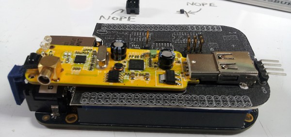
[N8VI] is working on a software defined radio cape for a BeagleBone. He was a bit concerned about a few caps getting in the way of a board stack. This was tested by printing out a bit of plastic in the shape of the new board, adding header spacers and parts that might be troublesome.

While the idea is great, there’s not much in the way of a software solution or a toolchain to make plastic copies of completed boards. We know rendering 3D objects from KiCAD is rather easy, but there aren’t many tools available for those of us who are still stuck with Eagle. If you know of a way to print populated boards, drop a note in the comments.

Midwest RepRap Festival, March 20-22nd

Right now there are two emails in my inbox inviting me to 3D printer conventions. If you’re not familiar with how these cons go, here’s a quick recap: a bunch of 3D printer manufacturers set up their booths the day before, put a printer behind an acrylic enclosure, start a very complex print, and come back the next day. This printer finally completes the print sometime Sunday afternoon, a bunch of people walk by the booths, and the entire venue is filled with enough morose faces as to be comparable to one of the higher circles of hell.

The Midwest RepRap Festival is not this con. It is, to the best of my knowledge, the only 3D printing convention that isn’t a trade show. It’s a blast, it’s March 20th through the 22nd, and we’re going to be there.

This will be our second expedition to the MRRF. Last year we saw 3D printed resin molds, and a strange Core XZ printer from [Nicholas Seward], the mind that brought you the odd Reprap Wally and Simpson. The most interesting man in the universe was there with a Smoothieboard. There were talks on 3D Bioprinting by [Jordan Miller] from Rice University, and everyone ate 3D printed waffles. If you’re looking for the possibilities 3D printing offers, this is the con to go to. If you’re looking for people to sell you stuff, look elsewhere.

This event is organized by the folks at SeeMeCNC, and it will be held on their home turf of Goshen, Indiana. Yes, you will be passing Amish buggies on the way to the event. Even though the MRRF is being held in the middle of nowhere, it was absolutely shocking how many people turned up last year and how good the con was. To put this in perspective, I’m driving nine hours to MRRF, and going to Maker Faire NYC takes me four hours. If I had to choose one 3D printing event to go to, this would be the one. That’s not just because I’m told there will be a t-shirt cannon at MRRF.

The event is free and open to everybody. You can just show up, although it would be a good idea to register. You’ll see the World’s Largest 3D Printed Trash Can. Yes, I’m serious. Call Guinness.

Face Recognition For Your Next Con

[jwcrawley] is busy planning for the Makevention coming up in Bloomington, Indiana in late August. One problem when working any con is manning the door; it’s a good idea to know how many people are there, and you can’t double count people. Previously, the volunteers used dead trees to estimate how many people have turned up. This year they might go with a more technological solution: face recognition and tracking.

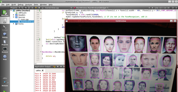
The project is called uWho, and it uses the faceRecognizer class in OpenCV. The purpose of the entire project is to identify who someone is from previous frames. If your face is unknown to the program, your likeness – rather, a few points of data – are added to the database of faces. It’s simple, and according to [jwcrawley], it works.

While this is technically the best way to count how many unique people show up to Makevention, there will be some discussions to see if this solution is appropriate. The program only saves unique data from a face locally, and does nothing online. It’s less evil than whatever Facebook does, but there are obvious privacy implications here.

Link to the Makevention.