E-reader Becomes Sailplane And Paraglider Computer

sail [Tweepy] flies unpowered aircraft, and he’d like to use the XCSoar flight computer app for gliders, sailplanes, and paragliders, but couldn’t find any hardware. XCSoar is an amazing app that can keep track of terrain, route, thermals, and a whole bunch of other variables that make flying more enjoyable, but running it on a device useful for a hang glider pilot is a challenge.

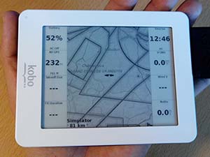
He eventually found a nearly perfect device in the Kobo mini e-reader. It’s e-ink, so it’s sunlight readable, uses a glove-compatible resistive touchscreen, runs Android, and is dirt cheap. The only thing lacking was a GPS receiver. What was [Tweepy] to do? Mod an e-reader, of course.

The electronic portion of the mod was simple enough; serial GPS units can be found just about everywhere, and the Kobo has a serial headers on the board. The case, however, required a bit of thingiverseing, and the completed case mod looks fairly professional.

With a few software updates, new maps, and of course the phenomenal XCSoar app, [Tweepy] had an awesome flight computer for under 100 Euro. The only thing missing is an integrated variometer, but a Game Boy will work in a pinch.

OpenExposer, The DIY SLA Printer

printer

Precisely applied ultraviolet light is an amazing thing. You can expose PCBs, print 3D objects, and even make a laser light show. Over on the Projects site, [Mario] is building a machine that does all of these things. It’s called the OpenExposer, and even if it doesn’t win the Hackaday Prize, it’s a great example of how far you can go with some salvaged electronics and a 3D printer.

The basic plan of the OpenExposer is a 3D printer with a small slit cut into the bed, and a build platform that moves in the Z axis. The bed contains a small UV laser and a polygon mirror ripped from a dead tree laser printer. By moving the bed in the Y direction, [Mario] shoot his laser anywhere on an XY plane. Put a tank filled with UV curing resin on the bed, and he has an SLA printer. Put a mounting bracket on the bed, and double-sided PCBs are a cinch.

The frame is made of 3D printed parts and standard RepRap rods, with the only hard to source component being the polygonal mirror. These can be sourced from scrounged laser printers, but there’s probably some company in China that will sell them bulk. The age of cheap SLA printers is dawning, friends. Video below, github here.

Continue reading “OpenExposer, The DIY SLA Printer”

A Smart Clothes Dryer

dryer6 
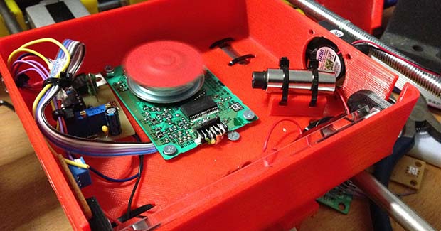
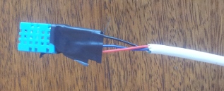
Here’s a question that will rack your brain: does your clothes dryer stop when the clothes are dry? It seems if you have a machine that guzzles power for one single purpose, you’d like it to stop when its job is done, or for the sake of convenience, keep going until the clothes are dry. Temperature and humidity sensors are cheap, and if you don’t have an auto sensing clothes dryer, a DIY smart clothes dryer seems both efficient and convenient. [Editor from the future: link rot, seems to be here now.]

[Andy] figured when clothes are dry, they stop emitting moisture. Based on that premise, he could monitor the operation of a clothes dryer and either shut off the machine or send a message that it’s time to take the clothes out. It’s a simple enough idea, and with an Arduino and a DHT11 temperature and humidity sensor, it was pretty easy to put together.

The clothes dryer used for this experiment was a self-ventilating model that doesn’t vent to the outside. Instead, it condenses the water in your towels and jeans into a tub to be emptied by hand later. This might introduce a little error into tests, but [Andy] did come up with a way to mount the temperature sensor without modifying his dryer in any way. From the initial data, the ventless dryer might be introducing a little experimental error, but it’s still too good of an idea to not try out with a traditional dryer that vents to the outside. Here’s the code should you want to try this yourself.

A Huge, Lightweight Wooden Quadrotor

quad_1

[Robert] once built a quadcopter frame by sawing laminate floor tile. It worked, we’re taking the lack of pictures of this build as evidence of how ugly it was. His latest design used a much better looking material – laser cut plywood – and the finished product is very strong and lightweight, even compared to commercial frames made with glass or carbon fiber and epoxy.

Although the design went smoothly thanks to some Solidworks skills, actually cutting the frame from 3mm birch ply resulted in a few issues. The cheap laser cutter used for cutting include some bottom of the line software called LaserWorksV5. There is a kerf compensation feature, called ‘sew compensation’ in the software’s native Chinglish. The software would always crash whenever it tried to calculate the compensation for circles. [Robert] spent two hours figuring this problem out, and in the end needed to break out a piece of sand paper to get a nice interlocking fit.

The completed frame bolts together without any glue at all, and the best part about it is the weight – only 167 grams. Compare that to a similarly sized glass fiber frame, and [Robert]’s shaved at least 200 grams off his finished build.

The Electrostatic Theory Of Metal Whiskers

wiskers
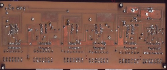
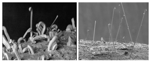
Thanks to that wonderful ROHS stuff the EU passed more than a decade ago, we should be seeing a few high-profile failures of electronic components due to tin whiskers. These tiny hair-like extrusions of metal found most commonly in lead-free solder have destroyed billion dollar satellites and shut down nuclear reactors, despite no one knowing exactly how these whiskers form. Now there’s a new theory of metal whisker formation (abstract, unless you have access to APS) that actually has predictive power. Here’s the free version of the paper

[V. G. Karpov] from the University of Toledo suggest these whiskers are formed by differences in charge induced by metallurgical anomalies – contamination, differences in the grain of the solder, and oxides. Because of the difference in charge, the whiskers are extruded, for lack of a better word, out from the surface of the solder.

The theory of whisker growth is generally consistent with observed rates of whisker growth and other properties. With this theory, it should even be possible to grow tin whiskers. Why anyone would want to do that other than, ‘because it’s cool’ is anyone’s guess, but there you go.

Running Minecraft On Two Routers

router

[CNLohr] is no stranger to running Minecraft on some weird hardware. Earlier, he built this Linux powered microscope slide… thing to toggle LEDs with redstone levers in Minecraft. Figuring if Minecraft could run on an AVR, he decided to try the same thing on a router, a TP-LINK TL-WR841N to be specific. Like the microscope slide running Linux, this proved to be an easy task. [CNLohr] had another router he could run Minecraft on, and this one could also punch wood. There really was only one thing for him to do.

Like the microscope slide and the wireless router, [CNLohr]’s CNC router is now running a Minecraft server. The phrase, “because it’s there” comes to mind. When connected to the CNC server, the player controls a snow golem (a snowman with a jack ‘o lantern head) with a carrot. Wherever the snow golem goes, the tool head follows, allowing him to carve objects in the world, and on a sheet of MDF secured in the CNC machine.

It’s certainly an odd build, but [CNLohr] was able to carve out a pixeley, blocky Hackaday logo with the snow golem controlled CNC machine. Code here, video below.

Continue reading “Running Minecraft On Two Routers”

The Design And Fabrication Of A Digital Clock

boarddesign

This clock is the first thing that [Kevin] ever made, way back before the Arduinofication of making, and long before the open hardware community exploded, and before the advent of cheap, custom PCBs. It’s an elegant design, with six seven-segment displays, a time base derived from line frequency, controlled entirely by 74-series logic chips. There was only one problem with it: it kinda sucked. Every so often, noise would become a factor and the time would be displayed as 97:30. The project was thrown in the back of the closet, a few revisions were completed, and 13 years later, [Kevin] wanted to fix his first clock.

The redesign used the same 1Hz timebase to control the circuitry, but now the timebase is controlled by a DS3231 RTC with an ATtiny85. The bridge rectifier was thrown out in favor of a much simpler 7805 regulator, and a new board was designed and sent off to OSHPark. Oh, how times have changed.

With the new circuitry, [Kevin] decided to construct a new case. The beautiful Hammond-esque enclosure was replaced with the latest and greatest of DIY case material – laser cut acrylic. Before, [Kevin] would put a jumper on the 1Hz timebase derived from the line frequency to set the clock – a task that makes plugging a clock in exactly at midnight a much simpler solution. Now, the clock has buttons to set the hours and minutes. Much improved, but still an amazing look at how far DIY electronics have come in a little over a decade.