Analog Tank Driving Simulator Patrols A Tiny Physical Landscape

How do you build a practical tank-driving simulator in the 1970s, when 3D computer-generated graphics are still just a fantasy of the future? If you’re a European tanker school, the solution is to use a large CNC machine to drive a camera around a miniature terrain model (German, translated). In the video after the break, [Tom Scott] takes it for a test drive.

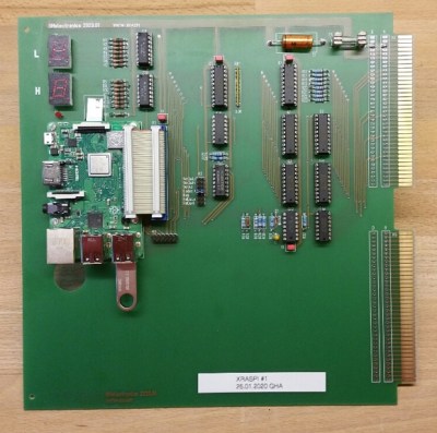
The old computer was replaced with a Raspberry Pi
The original computer was replaced with a Raspberry Pi

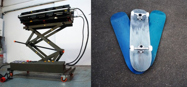
Developed in France, the simulator provided a safer and more cost-effective way for teaching new trainees the basics of driving Centurion, Leopard 2, or Panzer 68 tanks. The trainee sits in a realistic “cockpit” mounted on a hydraulically-operated motion platform, with a TV screen in front of his face, which is connected to a camera mounted on a large gantry-style CNC platform.

The camera’s lens is mounted just above a pivoting metal foot which slides across the 12 m-long terrain model and sends its angle to the hydraulic system. It will even alter the tank’s handling based on its current position on the model to simulate different surfaces like dirt, snow, or asphalt.

The last of these systems remained in use until 2004 at the military training center in Thun, Switzerland, before being saved by the Swiss Military Museum from being scrapped. The original 70s computer, electronics, and hydraulics finally gave out, so the museum undertook a complete refurbishment of the system to return it to working order for museum visitors. It was kept as original as possible, but parts for the original computer could not be found, so it was replaced with a Raspberry Pi and custom interface board.

Over three decades, these simulators probably trained a few thousand tank drivers, and even with limited technology did an excellent job of preparing trainees for the real thing. Besides providing training for operators, drivers and pilots, simulators are also just plain fun. We’ve seen some impressive home built simulator including a  A-10 Warthog, an F-15 sim built from an actual wreckage, and even a starship’s bridge.

Continue reading “Analog Tank Driving Simulator Patrols A Tiny Physical Landscape”

Cutting A Wearable Display In Half Is Harder And Simpler Than It Seems

In the world of hardware hacking, you sometimes spend a ridiculous amount of time debugging a problem, only to find a simple solution that was right in front of you the whole time. [Zack Freedman] got a good dose of this while building the Optigon V2, a modified Epson Moverio wearable display he uses as a teleprompter in all his videos. He prefers having the teleprompter over his left eye only, but the newer version of the Moverio would shut off both sides if one is disconnected, so [Zack] needed a workaround.

Looking for some help from above, [Zack] requested developer documentation for the display module from Epson, but got declined because he wasn’t a manufacturer or product developer. Luckily, a spec sheet available for downloaded from the Epson website did contain a lot of the information he needed. An STM32 monitored the temperature of each display module over a pair of independent I2C interfaces, and would shut down everything if it couldn’t connect to either. This led [Zack] to attempt to spoof the I2C signals with an ATmega328, but it couldn’t keep up with the 400 kHz I2C bus.

However, looking at the logs from his logic analyzer, [Zack] found that the STM32 never talked to both display modules simultaneously, even though it is capable of doing so. Both displays use the same I2C address, so [Zack] could simply connect the two I2C buses to each other with a simple interface board, effectively making the left display “spoof” the signals from the right display.

Wearable displays need some fancy optics to be practical, you can’t just stick an OLED to your face. Two other interesting projects from [Zack] are his modular mechanical keyboard and the Gridfinity 3D printed storage system.

Continue reading “Cutting A Wearable Display In Half Is Harder And Simpler Than It Seems”

The TAK Ecosystem: Military Coordination Goes Open Source

In recent years you’ve probably seen a couple of photos of tablets and smartphones strapped to the armor of soldiers, especially US Special Forces. The primary app loaded on most of those devices is ATAK or Android Tactical Assault Kit. It allows the soldier to view and share geospatial information, like friendly and enemy positions, danger areas, casualties, etc. As a way of working with geospatial information, its civilian applications became apparent, such as firefighting and law-enforcement, so CivTAK/ATAK-Civ was created and open sourced in 2020. Since ATAK-Civ was intended for those not carrying military-issued weapons, the acronym magically become the Android Team Awareness Kit. This caught the attention of the open source community, so today we’ll dive into the growing TAK ecosystem, its quirks, and potential use cases.

Tracking firefighting aircraft in 3D space using ADS-B (Credit: The TAK Syndicate)

Continue reading “The TAK Ecosystem: Military Coordination Goes Open Source”

Plotter Churns Out Labels With Roll Of Tape

Like it or not, organizing your workspace from time to time is a necessary chore. Labels can go a long way towards taming the most unruly of benches, but writing them out by hand isn’t exactly ideal. Looking for something a bit neater, [sandy] built a simple pen plotter to write labels on a roll of tape.

Pen plotter writing on roll of masking tape

The plotter uses the usual 3D printer components like steppers, drivers, belts, and rails. The tape holder is printed with flexible arms for a tight grip, and a servo is used to raise and lower the pen while writing.

The custom control board includes an Arduino Nano clone and a pair of stepper drivers, and an optional Bluetooth module and can be configured for a variety of machine control applications. A pair of Android apps are used to generate and send the G-code from a phone to the GRBL firmware loaded on the Arduino.

This seems to fall in the category of “entry-level” custom automation tools which help to save some time and effort on repetitive tasks without blowing the budget. We would include the various component tape cutters we’ve seen in this category, as well as smart build platform for manual PCB assembly

3D Printing A Prosthetic-Compatible Golf Club

Relearning an old sport, or starting a new one, can be challenging for amputees. Besides the obvious physical aspects, custom prosthetics or adaptors might need to be made and fitted, which can be very expensive. With the power of 3D printing and some machining, [Ian Davis] was able to build a custom prosthetic golf club to get a quadruple amputee back on the greens.

The recipient of this prosthetic lost both hands above the wrists, so [Ian] had to come up with a mechanism that could hold the club and mimic wrist motion throughout the swing. He was able to achieve this motion with a simple four-plate hinge for each arm. For optimal ergonomics, [Ian] also added two-axis adjustability, with only a single bolt needing to be loosened per axis. A standard golf club can be used and is clamped in the printed holders.

Machined prosthetic sockets were used to allow quick connection to the user’s existing prosthetic forearms. Theoretically, this should also allow him to switch clubs without excessive hassle. [Ian], an amputee himself, has used his engineering skills to build a series of prosthetic hands and even a custom controller mod to get back to gaming with fewer flesh fingers.

Continue reading “3D Printing A Prosthetic-Compatible Golf Club”

Magnetic Gearbox Can Go Fast But Not Hard

3D printed gearboxes are great for experimental designs, but due to roughness and inaccuracies in the printed surfaces, they can wear quickly and be rather noisy. As a possible alternative, [Resetman] is experimenting with magnetic 3D printed gearboxes that work without physical contact between the rotating wheels, and can also be “geared” for different ratios in some interesting ways.

Naturally, two closely spaced wheels with magnets will interact with each other, with the ratio defined by the number of magnets on each wheel. A much less obvious implementation is a second-order radial flux coaxial magnetic gearbox. It works similar to a normal planetary gearbox, with an outer and inner wheel containing magnets, and an intermediate ring known as a flux modulator, containing equally spaced pieces of ferromagnetic steel metal. In [Resetman] demonstration, the flux modulator is just a 3D printed ring screws around its circumference.

The most obvious disadvantage is of course severely limited torque transfer. [Resetman] could easily accelerate the sun wheel to 12,000 RPM if the flux modulator is accelerated slowly, but any sudden changes in speed would cause it to lose synchronization. Of course, you can consider this a torque-limiting feature for certain use cases. With a bit of testing, he determined the torque limit at a 1:4 ratio was a meager 0.05 Nm. This could be increased by some optimization, for example rearranging the magnets to form Halbach arrays, and reducing the air gaps between the components.

Magnetic gearboxes are nothing new, we’ve featured another demonstrator before, and even did an “Ask Hackaday” on the subject. What would you use these for? Let us know below.

Continue reading “Magnetic Gearbox Can Go Fast But Not Hard”

Rolling Sphere Robotic Arm Seems Serpentine

Hinge joints are usually the simplest to use for robotic applications, but if you want motion that looks more organic, rolling joint (or rolling contact) mechanisms are worth a look. [Skyentific] is experimenting with this mechanism and built a 6-degree-of-freedom robotic arm with it.

The mechanism doesn’t necessarily need the physical surfaces to roll across each other to work, and you can get to two degrees of freedom with the virtual rolling sphere mechanism. [Skyentific] demonstrates how these work with both cardboard cutouts and 3D printed models. Stacking three of these mechanisms on top of each other, with each stage driven by three Dynamixel servos, the motion seems almost serpentine.

Since the servos are driving the small bottom linkages of each stage, they are operating at a significant mechanical disadvantage. The arm can just barely keep itself upright on top of the table, so [Skyentific] mounted it upside down to the bottom of the table to reduce the load of its weight. With the front stage removed, the load is significantly reduced, and it doesn’t struggle as much.

An interesting advantage of this mechanism is that there is always a straight path down the center for cabling. The length of this line between the two plates remains the same throughout the entire range of motion, so it can also be used to route a rigid drive shaft. This is actually what was done on the LIMS2-AMBIDEX robot to rotate its hand, and is also where saw this mechanism for the first time. Interestingly, that implementation didn’t drive the linkages themselves, but used tension cables around the mechanism. We also see this in a very similar tentacle robot, so it might be a better option.

Continue reading “Rolling Sphere Robotic Arm Seems Serpentine”