solenoid wound pickup coil next to a selection of bolts and a steel rod

The Barkhausen Effect: Hearing Magnets Being Born

The Barkhausen effect — named after German Physicist Heinrich Barkhausen — is the term given to the noise output produced by a ferromagnetic material due to the change in size and orientation of its discrete magnetic domains under the influence of an external magnetic field. The domains are small: smaller than the microcrystalline grains that form the magnetic material, but larger than the atomic scale. Barkausen discovered that as a magnetic field was brought close to a ferrous material, the local magnetic field would flip around randomly, as the magnetic domains rearranged themselves into a minimum energy configuration and that this magnetic field noise could be sensed with an appropriately arranged pickup coil and an amplifier. In the short demonstration video below, this Barkhausen noise can be fed into an audio amplifier, producing a very illustrative example of the effect.

One example of practical use for this effect is with non-destructive testing and qualification of magnetic structures which may be subject to damage in use, such as in the nuclear industry. Crystalline discontinuities or impurities within a part under examination result in increased localized mechanical stresses, which could result in unexpected failure. The Barkhausen noise effect can be easily leveraged to detect such discontinuities and give the evaluator a sense of the condition of the part in question. All in all, a useful technique to know about!

If you were thinking that the Barkhausen is a familiar name, you may well be thinking about the Barkhausen stability criterion, which is fundamental to describing some of the conditions necessary for a linear feedback circuit to oscillate. We’ve covered such circuits before, such as this dive into bridge oscillators.

Continue reading “The Barkhausen Effect: Hearing Magnets Being Born”

Hackaday supercon badge PCB showing illuminated activity lights after being loaded with a punch card

Supercon Badge Reads A “Punch” Card

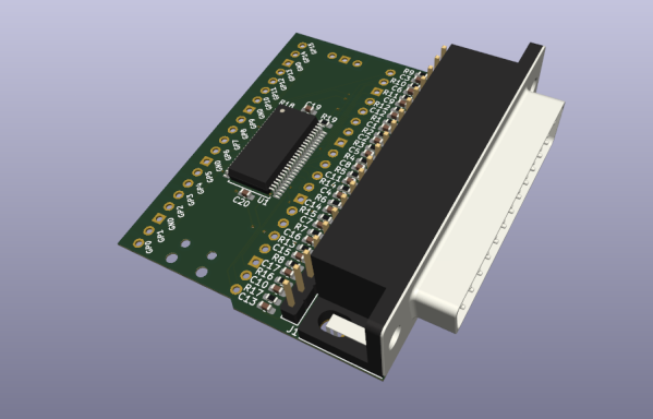
This year’s Hackaday Supercon, the first since 2019 thanks to the pandemic, was a very similar affair to those of the past. Almost every hardware-orientated hacker event has its own custom electronic badge, and Supercon was no different. This year’s badge is a simulation platform for a hypothetical 4-bit CPU created by our own [Voja Antonic], and presented a real challenge for some of the attendees who had never touched machine code during their formative years. The challenge set was to come up with the most interesting hack for the badge, so collaborators [Ben Hencke] and [Zach Fredin] set about nailing the ‘expandr’ category of the competition with their optical punched card reader bolt-on.

Peripheral connectivity is somewhat limited. The idea was to build a bolt-on board with its own local processing — using a PixelBlaze board [Ben] brought along — to handle all the scanning details. Then, once the program on the card was read, dump the whole thing over to the badge CPU via its serial interface. Without access to theirPrinted paper faux punch card showing read LEDs and an array of set and reset bits of the encoding usual facilities back home, [Ben] and [Zach] obviously had to improvise with whatever they had with them, and whatever could be scrounged off other badges or other hardware lying around.

One big issue was that most people don’t usually carry photodiodes with them, but luckily they remembered that an LED can be used as a photodiode when reverse-biased appropriately. Feeding the signal developed over a one Meg resistance, into a transconductance amplifier courtesy of a donated LM358 there was enough variation for the STM32 ADC to reliably detect the difference between unfilled and filled check-boxes on the filled-in program cards.

The CPU required 12-bit opcodes, which obviously implies 12 photodiodes and 12 LEDs to read each word. The PixelBlaze board does not have this many analog inputs. A simple trick was instead of having discrete inputs, all 12 photodiodes were wired in parallel and fed into a single input amplifier. To differentiate the different bits, the illumination LEDs instead were charlieplexed, thus delivering the individual bits as a sequence of values into the ADC, for subsequent de-serialising. The demonstration video shows that it works, with a program loaded from a card and kicked into operation manually. Such fun!

Punch cards usually have a hole through them and can be read mechanically, and are a great way to configure testers like this interesting vacuum valve tester we covered a short while back.

Continue reading “Supercon Badge Reads A “Punch” Card”

DIY equatorial mount

A DIY Equatorial Mount Using Harmonic Drives

As an amateur astrophotographer will tell you, you just don’t get to capture the really interesting objects without spending a ton of money on some decent pieces of kit. Telescope aside, there really is a surprising amount of complexity, weight, and associated costs with the telescope mount alone, let alone one that is capable of any sort of programmable tracking. [Alan (Jialiang) Zhao] clearly wanted to up their game, and having suffered some of the shortcomings of their Sky-Watcher HEQ-5 pro Equatorial mount decided to go ahead and build an open-source mount, Alkaid, which hopefully works a bit better for them.

In simple terms, the difficulty of photographing an extremely dim, distant object (or one that is larger but diffuse) is that the camera sensor needs to spend a significant amount of time signal-averaging, to gather enough lightSheet of parts freshly water cut from aluminium plate for anything to be seen at all, through the noise. But, this ball of rock we sit on is rotating constantly, so the only solution is to track the object of interest, to compensate. This is referred to as equatorial tracking, and allows the rotation of the Earth to be compensated for during a long exposure.

The design of each of the two axes revolves (sorry!) around the use of a NEMA-17 stepper motor with a 27:1 planetary gearbox, driving into a harmonic reducer gearbox. Harmonic drives (aka strain wave drives) are pretty neat, working on the principle of a fixed, but circularly distorting ring gear that transmits torque from the inside surface to the outside, with almost no backlash. They are expensive parts, but for a super smooth movement, this is what you want. The huge output torque they allow, meant that [Alan] was able to build a mount for a heavy telescope without any counterbalances. Structurally, the whole thing is constructed from 10 mm thick aluminium plates that were cut with a waterjet and subsequently milled to finish. Continue reading “A DIY Equatorial Mount Using Harmonic Drives”

Trigger Your Home Automation Routines With Home Buttons

Home automation systems are all well and good, so long as the person who built it all is around to drive it. Let’s face it, they’re quite often a complex web of interconnected systems, all tied to the specifics of one’s home — and someone less familiar with it all could get a little irritated if, on a chilly day, the interface to the boiler is via a Python script, and something won’t work. Just saying. Home Buttons by [Matej Planinšek] over on Hackaday.IO is a nicely polished project, which aims to take some of the hackiness out of such automation by providing a sleek front end to those automation routines, enabling anyone to rock on over and set one in action without hassle.

Internal PCB shown in the foreground, with the complete unit behind.The PCB is based around the ESP32-S2-mini which deals with WiFi connectivity and integration with Home Assistant using the usual MQTT protocol. We expect integration with other flavors of home automation would not be difficult to achieve. The center of the unit holds a simple E-Ink display, for that low-standby power. Specifically, the unit chosen is a Good Display GDEY029T94 2.9″ which this scribe can confirm is easy to interface and pretty cheap to purchase from the usual Chinese online vendors. This was matched up with six clicky Alps SKRB-series low-profile tact switches, which sit on either side of the display, and corresponds to a flexure-type affair on the 3D printed front casing. Neat and simple.

The PCB design was provided in Altium format, which you can find on the project GitHub page. This shows a straightforward design, with a few nice little details here and there. The internally mounted 18650 cell is reportedly good for at least a year of operation, but when time, it can be charged via USB. A Xysemi XB8608AF (PDF) protection chip provides appropriate limiting for the 18650 cell, shielding it from the perils of overcharging, discharging, and whatnot. Not that that is likely in this current setup. A Sensiron SHTC3 humidity and temperature sensor is also in there, hanging off the I2C bus, which makes sense for this application.

Home Automation hacks are plenty on these pages, like this scroll-wheel interface, for instance. If all this stuff is looking quite overbearingly complicated to get into, how about starting with a Pico W?

3D Printing With A Drone Swarm?

Even in technical disciplines such as engineering, there is much we can still learn from nature. After all, the endless experimentation and trials of life give rise to some of the most elegant solutions to problems. With that in mind, a large team of researchers took inspiration from the humble (if rather annoying) wasp, specifically its nest-building skills. The idea was to explore 3D printing of structures without the constraints of a framed machine, by mounting an extruder onto a drone.

As you might expect, one of the most obvious issues with this attempt is the tendency of the drone’s to drift around slightly. The solution the team came up with was to mount the effector onto a delta bot carrier hanging from the bottom of the drone, allowing it to compensate for its measured movement and cancel out the majority of the positional error.

The printing method relies upon the use of two kinds of drone. The first done operates as a scanner, measuring the print surface and any printing already completed. The second drone then approaches and lays down a single layer, before they swap places and repeat until the structure is complete.

Multiple drones can print simultaneously, by flying in formation. Prints were demonstrated using a custom cement-like material, as well as what appeared to be expanding foam, which was impressive feat to say the least.

The goal is to enable the printing of large, complex shaped structures, on any surface, using a swarm of drones, each depositing whatever material is required. It’s a bit like a swarm of wasps building a nest, into whatever little nook they come across, but on the wing.

We’ve been promised 3D printed buildings for some time now, and while we’re not sure this research is going to bring us any closer to living in an extruded house, we’re suckers for a good drone swarm here at Hackaday.

Continue reading “3D Printing With A Drone Swarm?”

This Infinity Dodecahedron Build Shows All The Tricks

The infinity dodecahedron is one of those super eye-catching builds that many of us hardware hackers have on our ‘build one day’ project list. The very thought of actually doing it strikes a little fear into the heart of even the most intrepid maker, once you start to think about all the intricate little details and associated ways it could all go horribly wrong. Luckily for us, [Hari Wiguna] has documented his latest build as a long video build log, showing lots of neat tricks and highlighting many problems along the way. With the eventual goal of removing many of the issues that make such a build tricky, [Hari] hopes to make it practically easy. Let’s see how that turns out!

HASL-finished castellated (half hole) edge contacts make butt-jointing a breeze

A common route for such a build relies on appropriately shaped 3D printed frame parts, with some kind of clear plastic for the 12 faces, and LED strips stuck to the inside of each of the 30 edges. Whilst this works, [Hari] thought he could do a bit better, using butt-jointed PCBs as the frame material.

The PCBs handily double up as something to solder LEDs onto (because that’s what PCBs are mostly intended for!) as well as a way to pass power and data signals around the frame in a minimally visible way. As will become obvious from the lengthy discussion in the video, a few simple tricks here and there are needed to make this strategy work. With the recent proliferation of PCB modules using castellated edges for termination, the usual Chinese PCB fab services have all started offering very good value services for this feature. Once a PCB feature that was a specialized (read that as ‘expensive’) offering, it is now quite affordable on your average maker’s budget.

Data path planning? Just use paper and tape!

One immediate practical issue was how to pass the data connection around from edge to edge, given that there are three edges per vertex. The solution [Hari] came up with was simple, just duplicate the signals on each end of the PCB, so the data out signal can be tapped from either end, as required.

Even with 3D printed jigs to hold the PCBs at just the right angles, there’s still some wiggle and a little risk of edges not quite aligning, due to accumulated errors around the frame. It did come together in the end, with the expected spectacular visuals. We’re sure many of you will be waiting for [Hari] to release the next version of the design to the community, hopefully with even more of the ease-of-build issues resolved, because we want one even more now.

Naturally, this is by no means the first infinity platonic solid we’ve seen, here’s a smaller one for starters. If you remove the mirrors and LEDs, then you’re just left with a plain old dodecahedron, like this cool folding project.

Continue reading “This Infinity Dodecahedron Build Shows All The Tricks”

Flux: A Forty Foot Long Kinetic Art Piece

No office space is complete without some eye-catching art piece to gawp at whilst you mull over your latest problem. But LED-based displays are common enough to be boring these days. Kinetic art pieces are where it’s at, and this piece called Flux is a perfect example.

Commissioned for the Toronto office of a very popular e-commerce platform and constructed by [Nicholas Stedman], Flux consists of twenty identical planks on the ceiling, arranged in a line forty feet long. Each plank has a pair of rotating prisms, constructed from a stack of foam sheets, finished with metallic paint. The prisms are spun by individual stepper motors, each of which is driven by a TMC2160-based module, making them whisper-quiet.

A simple 3D printed bracket holds a small PCB holding an AMS AS5600 rotary magnetic encoder, onto the rear of the stepper motor. This allows for closed-loop feedback to the shared Arduino, which is very important for a sculpture such as this. Each Arduino is hooked up to a Raspberry Pi, running a simple application written in node.js which is responsible for coordinating movement, as well as uploading updated firmware images as required. A simple, but very effective build, we think!

Even more fun are kinetic art installations that are reactive to some data source, such as Adad, which visualizes lightning strike data. If these builds are just too big and complex, we’ve seen many examples of smaller desktop toys, such as this 3D printed tumbling chain demo for example.

Continue reading Flux: A Forty Foot Long Kinetic Art Piece”