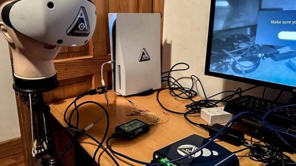
When the PlayStation VR2 headset was released, people wondered whether it would be possible to get the headset to work as a PC VR headset. That would mean being able to plug it into a PC and have it work as a VR headset, instead of it only working on a PS5 as Sony intended.
 Enthusiasts were initially skeptical and at times despondent about the prospects, but developer [iVRy]’s efforts recently had a breakthrough. A PC-compatible VR2 is looking more likely to happen.
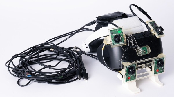
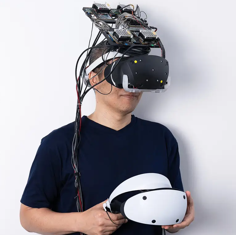
So far [iVRy] is claiming they have 6 DOF SLAM (Simultaneous Localisation and Mapping), Prox sensor, and stereo camera data.
Most of the juicy bits are paywalled behind [iVRy]’s Patreon. We’re hoping the jailbreak process will eventually be open-sourced.
The PS VR2 headset is quite unlike a PC VR headset in a number of ways, and it has not been historically easy to work with Sony’s products from a reverse-engineering perspective, whether it’s an attempt to improve the user experience of an annoying headset, or an attempt to understand the not-even-remotely-sanely-designed protocols behind the Sony Memory Stick. Getting the PS VR2 headset to work in a way it wasn’t intended was expected to be an uphill battle.
It’s not a finished job, but judging by the progress regularly shared on [iVRy]’s Twitter account, it might only be a matter of time.