BeagleBone Black And FPGA Driven LED Wall

LED Wall


This is 6,144 RGB LEDs being controlled by a BeagleBone Black and a FPGA. This gives the display 12 bit color and a refresh rate of 200 Hz. [Glen]’s 6 panel LED wall uses the BeagleBone Black to generate the image, and the LogiBone FPGA board for high speed IO.

[Glen] started off with a single 32 x 32 RGB LED panel, and wrote a detailed tutorial on how that build works. The LED panels used for this project have built in drivers, but they cannot do PWM. To control color, the entire panel must be updated at high speed.

The BeagleBone’s IO isn’t fast enough for this, so a Xilinx Spartan 6 LX9 FPGA takes care of the high speed signaling. The image is loaded into the FPGA’s Block RAM by the BeagleBone, and the FPGA takes care of the rest. The LogiBone maps the FPGA’s address space into the CPU’s address space, which allows for high speed transfers.

If you want to drive this many LEDs, you’ll need to look beyond the Arduino. [Glen]’s work provides a great starting point, and all of the source is available on Github.

[Thanks to Jonathan for the tip]

Designing A Front Panel For A DIY Project

DIY Front Panel


When building a one-off DIY project, appearances tend to be the least of our priorities. We just want to get the device working, and crammed into some project case. For those that like to build nicer looking prototypes [JumperOne] came up with a slick method of building a custom front panel for your DIY project.

The first step is to get the dimensions correct. You CAD tool will generate these from your design. [JumperOne] took these measurements into Inkscape, an open source vector graphics tool. Once it’s in Inkscape, the panel can be designed around the controls. This gets printed out and aligned on a plastic enclosure, which allows the holes to be marked and drilled.

With the electronics in place, the front panel gets printed again on a general purpose adhesive sheet. Next up is a piece of cold laminating film, which protects the label. Finally, holes are cut for the controls. Note that the display and LEDs are left covered, which allows the film to diffuse the light. The final result looks good, and can provide all the needed instructions directly on the panel.

[Thanks to Ryan for the tip]

Dirt Cheap Dirty Boards Offers Dirt Cheap PCB Fab

When your project is ready to build, it’s time to find a PCB manufacturer. There are tons of them out there, but for prototype purposes cheaper is usually better. [Ian] at Dangerous Prototypes has just announced Dirt Cheap Dirty Boards, a PCB fabrication service for times where quality doesn’t matter too much. [Ian] also discussed the service on the Dangerous Prototypes forum.

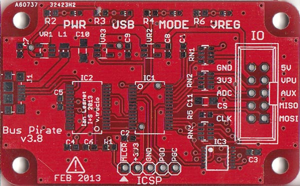
The boards are definitely cheap. $12 USD gets you ten 5 cm by 5 cm boards with 100% e-test and free worldwide shipping. You can even choose from a number of solder mask colors for no additional cost. [Ian] does warn the boards aren’t of the best quality, as you can tell in the Bus Pirate picture above. The silkscreen alignment has some issues, but for $1.2 a board, it’s hard to complain. After all, the site’s motto is “No bull, just crappy PCBs.”

The main downside of this service will be shipping time. While the Chinese fab house cranks out boards in two to four days, Hong Kong Post can take up to 30 days to deliver your boards. This isn’t ideal, but the price is right.

Open Source Power Line Communication

Power Line Communication Filtering


Since we all have wires running throughout our houses to provide mains power, there’s a number of devices that piggyback on mains lines for communication. For his thesis project, [Haris Andrianakis] developed his own power line communication system.

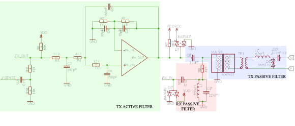
The basic principle of the system is to inject a signal onto the power lines at a much higher frequency than the 50 or 60 Hz of the AC power itself. Using both active and passive filters, the signal can be separated from the AC power and decoded. This system uses frequency-shift keying to encode data. This part is done by a ST7540 modem that’s designed for power line applications. The modem is controlled over SPI by an ATmega168 microcontroller.

[Haris]’ write up goes into detail about some of the challenges he faced, and how to protect the device from the high voltages present. The final result is a remote display for a weigh scale, which communicates over the power line. Schematics, PCB layout, and software are all available.

Taking Pictures With A DRAM Chip


DRAM Image

This picture was taken by using a DRAM chip as an image sensor (translated). A decapped 64k DRAM chip was combined with optics that could focus an image onto the die. By reading data out of the DRAM, the image could be constructed.

DRAM is the type of RAM you find on the RAM cards inserted into your motherboard. It consists of a massive array of capacitors and transistors. Each bit requires one transistor and one capacitor, which is quite efficient. The downside is that the memory needs to be refreshed periodically to prevent the capacitors from discharging.

Exposing the capacitor to light causes it to discharge faster. Once it has discharged past a certain threshold, the bit will flip from one to zero. To take a picture, ones are written to every bit in the DRAM array. By timing how long it takes a bit to flip from one to zero, the amount of light exposure can be determined. Since the DRAM is laid out in an array, each bit can be treated as a pixel to reconstruct the image.

Sure, modern CCDs are better, cheaper, and faster, but this hack is a neat way to totally re-purpose a chip. There’s even Turbo Pascal source if you’d like to recreate the project.

Thanks to [svofski] for the tip.

Powering A RPi With Hydrogen

raspberryHy

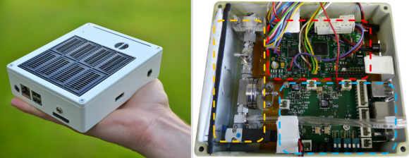
Looking for a new way to power your Raspberry Pi? The raspberryHy project aims to develop a small fuel cell designed for powering the credit card sized computer. It adds a proton exchange membrane (PEM) fuel cell, a battery, and custom control electronics to the Pi.

The system takes hydrogen in from a compressed hydrogen cartridge and feeds it through a regulator. This passes the hydrogen into the PEM fuel cell at the correct pressure, and creates a potential. The control electronics boost that voltage up to the 5 V required on the Pi’s USB port. There’s also an electronically controlled purge valve which periodically exhausts the fuel cell.

There’s a few reasons you might want to run your Pi with hydrogen. Run time of the fuel cell is limited only by the amount of hydrogen you can store. In theory, you could connect a large cylinder for very long run times. Combined with a battery, this could be quite useful for running Pis in remote locations, or for long-term backup power. The raspberryHy will be presented at Hannover Fair 2014 this month.

Arduino Controlled Dahlander Motor Switch


Dahlander Switch

[Jean-Noel] is fixing a broken Lurem woodworking machine. This machine uses a three-phase Dahlander motor, which has three operation modes: stop, half speed, and full speed. The motor uses a special mechanical switch to select the operating mode. Unfortunately, the mechanical bits inside the switch were broken, and the motor couldn’t be turned on.

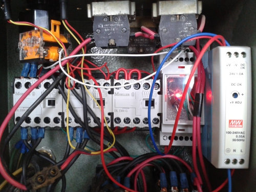
To solve the problem without sourcing a new switch, [Jean-Noel] built his own Arduino based Dahlander switch. This consists of three relays that select the wiring configuration for each speed mode. There’s also a button to toggle settings, and two lamps to show what mode the motor is currently in.

The Arduino runs a finite-state machine (FSM), ensuring that the device transitions through the modes in the correct order. This is quite important, since the motor could be damaged if certain restrictions aren’t followed. The state machine graph was generated using Fizzim, a free tool that generates not only FSM graphs, but also Verilog and VHDL code for the machines.

The final product is housed in a DIN rail case, which allows it to be securely mounted along with the rest of the wiring. The detailed write-up on this project explains all the details of the motor, and the challenges of building this replacement switch.