If you are a gardener, you’ll know only too well the distress of seeing your hard work turned into a free lunch for passing herbivorous wildlife. It’s something that has evidently vexed [Jim], because he’s come up with an automated Raspberry Pi-controlled turret to seek out invading deer, and in his words: “Persuade them to munch elsewhere”.
Before you groan and sigh that here’s yet another pan and tilt camera, let us reassure you that this one is a little bit special. For a start, it rotates upon a set of slip rings rather than an untidy mess of twisted cables, so it can perfom 360 degree rotations at will, then it has a rather well-designed tilting cage for its payload. The write-up is rather functional but worth persevering with, and he’s posted a YouTube video that we’ve placed below the break.
This is a project that still has some way to go, for example just how those pesky deer are to be sent packing isn’t made entirely clear, but we think it already shows enough potential to be worthy of a second look. The slip ring mechanism in particular could find a home in many other projects.
It’s worth reminding readers that while pan and tilt mechanisms can be as impressive as this one, sometimes they are a little more basic.
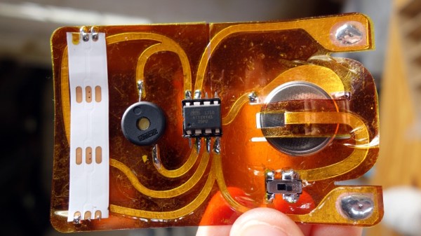
One of the first things anyone with an interest in electronics learns is the resistor colour code. The colour of the first band reveals the first figure, the second the subsequent figure, and the third a power-of-ten multiplier. At first you learn these colours, but eventually you just recognise the values through familiarity. You don’t have to think about multipliers when you see orange-orange-red, you just know that it’s a 3K3 resistor.
[Plusea] has come up with an entertaining interface for an ohmmeter, which instead of displaying the resistance on an LCD or a meter shows it as the colours of the code, via a set of addressable LEDs. The work is done by an ATtiny85 microcontroller, and the whole thing is mounted on a flexible PCB (fabrication of which is itself interesting, placing cut copper traces on a sheet of kapton and covering with a second kapton layer cut to be the solder mask). There is even a clever integration of a CR2032 battery holder from the PCB itself, though they admit that it could be made more compact with the use of SMD components instead of through-hole.
The write-up and associated photo album tells us a lot about the project, but is missing a crucial detail: a shot of it working. We’ll give them the benefit of the doubt on that front though, because we like the idea and its execution.
Strangely, this isn’t the first ohmmeter to use the resistor colour code in this way, we’ve previously brought you one featuring a light-up giant resistor.
If you are in the habit of seeking out abandoned railways, you may have stood in the shadow of more than one Victorian iron bridge. Massive in construction, these structures have proved to be extremely robust, with many of them still in excellent condition even after years of neglect.
A handsome riveted railway bridge, over the River Avon near Stratford-upon-Avon, UK.
When you examine them closely, an immediate difference emerges between them and any modern counterparts, unlike almost all similar metalwork created today they contain no welded joints. Arc welders like reliable electrical supplies were many decades away when they were constructed, so instead they are held together with hundreds of massive rivets. They would have been prefabricated in sections and transported to the site, where they would have been assembled by a riveting gang with a portable forge.
So for an audience in 2018, what is a rivet? If you’ve immediately thought of a pop rivet then it shares the function of joining two sheets of material by pulling them tightly together, but differs completely in its construction. These rivets start life as pieces of steel bar formed into pins with one end formed into a mushroom-style dome, probably in a hot drop-forging process.
A rivet is heated to red-hot, then placed through pre-aligned holes in the sheets to be joined, and its straight end is hammered to a mushroom shape to match the domed end. The rivet then cools down and contracts, putting it under tension and drawing the two sheets together very tightly. Tightly enough in fact that it can form a seal against water or high-pressure steam, as shown by iron rivets being used in the construction of ships, or high-pressure boilers. How is this possible? Let’s take a look!
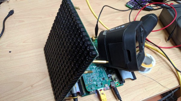
Ultrasonic phased arrays are one of the wonders of the moment, with videos of small items being levitated by them shared far and wide. We’ve all seen them and some of us have even wondered about building them, but what about the practical considerations? Just how would you drive a large array of ultrasonic transducers, and how would you maintain a consistent phase relationship between their outputs? It’s a problem [Niklas Fauth] has been grappling with over the three iterations so far of his ultrasonic phased array project, and you can follow his progress on the latest build.
The arrays themselves are a 16 by 16 grid of cheap ultrasonic transducers on a PCB, fed by HV583 high-voltage shift registers. These chips have proven to be particularly problematic, their drivers having a relatively high internal resistance which leaves them prone to overheating.
An interesting solution to a problem comes from the transducers having a polarity, but because it doesn’t matter in their usual application, that polarity not being marked. He’s overcome this by using the STM32 he has managing power alongside his BeagleBone to listen through a sensor as the ‘Bone supplies each transducer in turn with a known phase. An internal map can then be created, such that the appropriate phase can be applied on a transducer-by-transducer basis.
It’s the fascination with the subject that we find appealing, this is version three and version two worked. Most of us would make one and call it a day. It’s something we’ve seen before from [Niklas], after all this is someone who plays with turbomolecular pumps for fun. Meanwhile if you would like to learn more about ultrasonic arrays and acoustic levitation, it was the subject of one of this year’s Hackaday Belgrade talks.
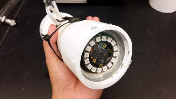
We are surrounded by sensors for all forms of environmental measurement, and a casual browse through an electronics catalogue can see an experimenter tooled up with the whole array for a relatively small outlay. When the environment in question is not the still air of your bench but the turbulence, sand, grit, and mud of a sea floor, that pile of sensors becomes rather useless. [Ellie T] has been addressing this problem as part of the study of hypoxia in marine life, and part of her solution is to create an underwater camera by encasing a Raspberry Pi Zero W and camera in a sturdy enclosure made from PVC pipe. She’s called the project LoBSTAS, which stands for Low-cost Benthic Sensing Trap-Attached System.
The housing is simple enough, the PVC has a transparent acrylic disk mounted in a pipe coupler at one end, with the seal being provided at the other by an expansion plug. A neopixel ring is mounted in the clear end, with the Pi camera mounted in its centre. Meanwhile the Pi itself occupies the body of the unit, with power coming from a USB battery bank. The camera isn’t the only sensor on this build though, and Atlas Scientific oxygen sensor completes the package and is mounted in a hole drilled in the expansion plug and sealed with silicone sealant.
When you have a complex task that would sap the time and energy of your microprocessor, it makes sense to offload it to another piece of hardware. We are all used to this in the form of the graphics chipsets our computers use — specialised processors whose computing power in that specific task easily outshines that of our main CPU. This offloading of tasks is just as relevant at the microcontroller level too. One example is the EM Microelectronics EM7180 motion co-processor. It takes input from a 3-axis gyroscope/accelerometer and magnetometer, acting for all intents and purposes as a fit-and-forget component. Given an EM7810, your host can determine its heading and speed at a simple command, with no need for any hard work.
[Kris Winer] used the EM7810, but frustrated at its shortcomings decided to create a more versatile alternative. The result is a small PCB holding a Maxim MAX32660 ARM Cortex M4F microcontroller and the relevant sensors, with the MAX32660’s increased power and integrated flash easily eclipsing the EM7810.
As a design exercise it’s an interesting read even if you have no need for one. His write-up goes into detail on the state of the motion coprocessor art, and then looks carefully at pushing the limits of what is possible using an inexpensive PCB fabrication house such as OSH Park — you can get this chip as a Wafer-Level Package (WLP) which is definitely off-limits. Even with the TQFN-24 he picked though, the result is a tiny board and we’re happy to see it as an entry in the Return of the Square Inch Project!
It is perhaps surprising how few projects like this one make it into our sphere, as a community we tend to focus upon making one processor do all the hard work. But with the ready availability of inexpensive and powerful devices, perhaps this is an approach that we should reconsider.
If you are in any way connected with radio, you will have encountered the low pass filter as a means to remove unwanted harmonics from the output of your transmitters. It’s a network of capacitors and inductors usually referred to as a pi-network after the rough resemblance of the schematic to a capital Greek letter Pi, and getting them right has traditionally been something of a Black Art. There are tables and formulae, but even after impressive feats of calculation the result can often not match the expectation.
The 30MHz low-pass filter, as QUCS delivered it.
Happily as with so many other fields, in recent decades the advent of affordable high-power computing has brought with it the ability to take the hard work out of filter design, Simply tell some software what the characteristics of your desired filter are, and it will do the rest. The results are good, and anyone can become a filter designer, but as is so often the case there remains a snag. The software calculates ideal inductances and capacitances for the desired cut-off and impedance, and in selecting the closest preferred values we modify the characteristics of the result and possibly even ruin our final filter. So it’s worth taking a look at the process here, and examining the effect of tweaking component values in this way.
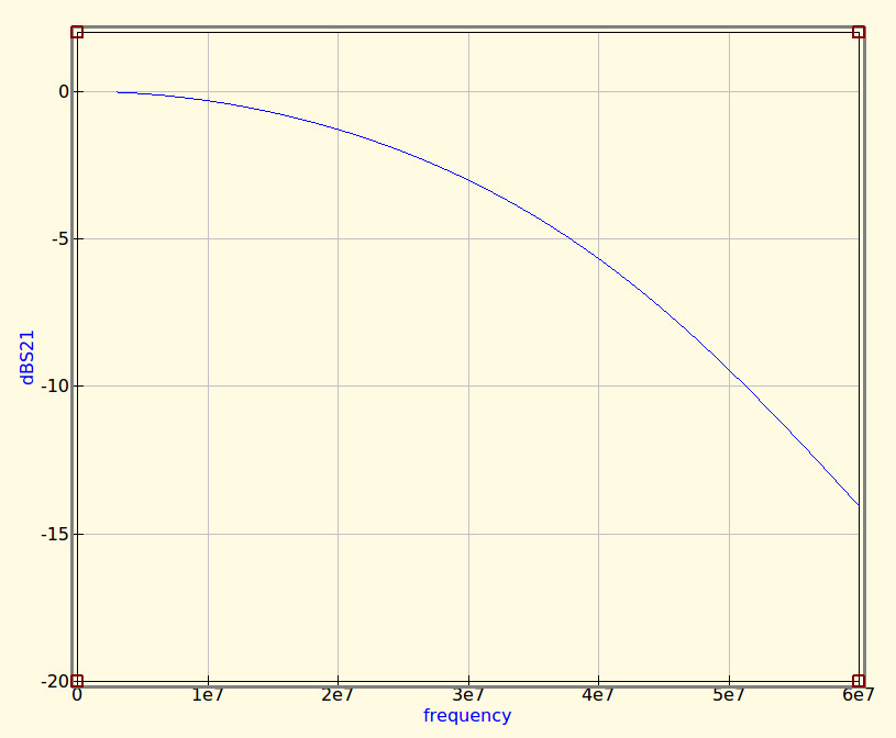
The idealised graph produced by QUCS for our filter.
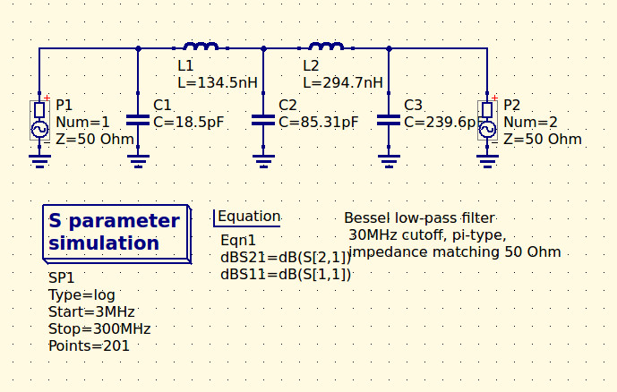
The filter we’re designing is simple enough, a 5th-order Bessel filter, and the software is the easy-to-use QUCS package on an Ubuntu Linux machine. Plug in the required figures and it spits out a circuit diagram, which we can then simulate to show a nice curve with a 3dB point right on 30MHz. It’s an extremely idealised graph, and experience has taught me that real-world filters using these designs have a lower-frequency cut-off point, but for our purposes here it’s a good enough start.
As previously mentioned, the component values are not preferred ones from a commercially available series, so I can’t buy them off the shelf. I can wind my own inductors, but therein lies a whole world of pain of its own and I’d rather not go there. RS, Mouser, Digikey, Farnell et al exist to save me from such pits of electronic doom, why on earth would I do anything else but buy ready-made?
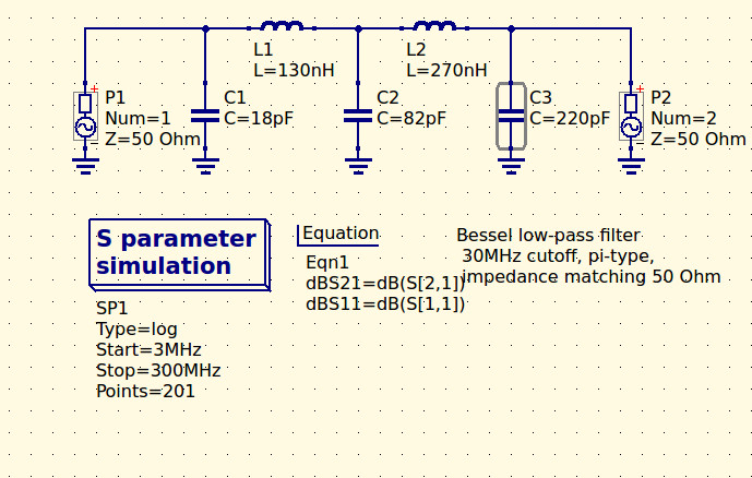
My revised filter circuit with off-the-shelf component values.
So each of the components in the above schematic needs moving up or down a little way to a preferred value. What effect will that have on the performance of my filter? Changing each value and re-running the simulation shows us the graph changing subtly each time, and it can sometimes be a challenge to adjust them without destroying the filter entirely. Particularly with the higher-order filters with more components in the network you can observe the effect of individual components on the gradient at different parts of the graph, but as a rule of thumb making values higher reduces the cut-off frequency and making them lower increases it. In my case I always pick higher values for that reason: my nearest harmonic I wish to filter is at double the frequency so I have quite some headroom to play with.
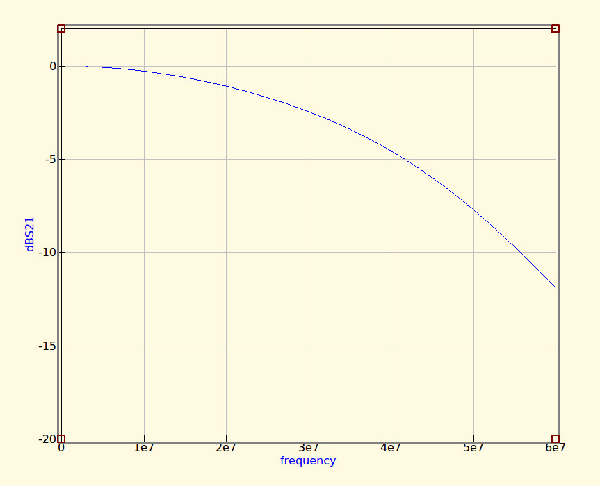
The revised curve from the filter with preferred values.
Having replaced my component values with preferred ones I can run the simulation again, and I can see from the resulting graph that I’ve been quite fortunate in not damaging its characteristics too much. As expected the cut-off frequency has shifted up a little, but the same curve shape has been preserved without any ripples appearing or it being made shallower.
If I were using this filter with a real transmitter I would ensure that I designed it with a cut-off at least a quarter higher than the transmission frequency. In practice I find the cut-off to be sharper and lower than the simulation leads one to expect, and for example, were I to use this one with a 30 MHz transmitter I’d find it attenuated the carrier by more than I’d consider acceptable. It must also be admitted that changing the component values in this way will also change the impedance of the filter from the calculated 50 ohms, however in practice this does not seem to be significant enough to cause a problem as long as the value changes are modest.
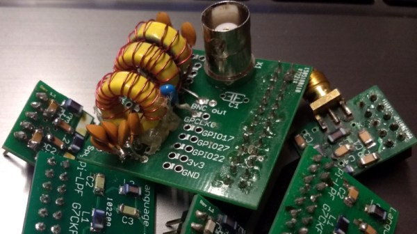
We haven’t made this filter, but in the past we’ve featured another one I did make, and by coincidence it was in the same frequency range. When I wrote a feature on automating oscilloscope readings, the example I used was the characterisation of a 7th-order 30 MHz low-pass filter. It might even be one of the ones in the header image, pulled from my random bag of filter boards for the occasion.