A Two Tapes Turing Machine

Though as with so many independent inventors the origins of computing can be said to have been arrived at through the work of many people, Alan Turing is certainly one of the foundational figures in computer science. His Turing machine was a thought-experiment computing device in which a program performs operations upon symbols printed on an infinite strip of tape, and can in theory calculate anything that any computer can.

In practice, we do not use Turing machines as our everyday computing platforms. A machine designed as an academic abstract exercise is not designed for efficiency. But that won’t stop Hackaday, and to prove that point [Olivier Bailleux] has done just that using readily available electronic components. His twin-tape Turing machine is presented on a large PCB, and is shown in the video below the break computing the first few numbers of the Fibonacci sequence.

The schematic is available as a PDF, and mostly comprises of 74-series logic chips with the tape contents being displayed as two rows of LEDs. The program is expressed as a pluggable diode matrix, but in a particularly neat manner he has used LEDs instead of traditional diodes, allowing us to see each instruction as it is accessed. The whole is a fascinating item for anyone wishing to learn about Turing machines, though we wish [Olivier] had given  us a little more information in his write-up.

That fascination with Turing machines has manifested itself in numerous builds here over the years. Just a small selection are one using 3D printing, another using Lego, and a third using ball bearings. And of course, if you’d like instant gratification, take a look at the one Google put in one of their doodles for Turing’s 100th anniversary.

Continue reading “A Two Tapes Turing Machine”

France Proposes Software Security Liability For Manufacturers, Open Source As Support Ends

It sometimes seems as though barely a week can go by without yet another major software-related hardware vulnerability story. As manufacturers grapple with the demands of no longer building simple appliances but instead supplying them containing software that may expose itself to the world over the Internet, we see devices shipped with insecure firmware and little care for its support or updating after the sale.

The French government have a proposal to address this problem that may be of interest to our community, to make manufacturers liable for the security of a product while it is on the market, and with the possibility of requiring its software to be made open-source at end-of-life. In the first instance it can only be a good thing for device security to be put at the top of a manufacturer’s agenda, and in the second the ready availability of source code would present reverse engineers with a bonanza.

It’s worth making the point that this is a strategy document, what it contains are only proposals and not laws. As a 166 page French-language PDF it’s a long read for any Francophones among you and contains many other aspects of the French take on cybersecurity. But it’s important, because it shows the likely direction that France intends to take on this issue within the EU. At an EU level this could then represent a globally significant move that would affect products sold far and wide.

What do we expect to happen in reality though? It would be nice to think that security holes in consumer devices would be neutralised overnight and then we’d have source code for a load of devices, but we’d reluctantly have to say we’ll believe it when we see it. It is more likely that manufacturers will fight it tooth and nail, and given some recent stories about devices being bricked by software updates at the end of support we could even see many of them willingly consigning their products to the e-waste bins rather than complying. We’d love to be proven wrong, but perhaps we’re too used to such stories. Either way this will be an interesting story to watch, and we’ll keep you posted.

Merci beaucoup [Sebastien] for the invaluable French-language help.

French flag: Wox-globe-trotter [Public domain].

OBD-Sniffing A Caddy PHEV

The Cadillac ELR is a plug-in hybrid car with a bit of class, it has the beating heart of a Chevy Volt in a nice coupĂ© body with some up-market styling and a nice interior. Since it wasn’t on the market for long and some consumers are still wary of cars with electric motors, it also represents something of a sweet spot: according to [Andrew Rossignol] you can pick them up for less outlay than you might imagine. He bought one, and being an inquisitive soul decided to probe its secrets through its OBD-II ports.

OBD-II sniffing is nothing especially new, but his write-up provides an interesting run-down of the methodology used to identify the different proprietary pieces of data that it makes available. His Python script attempted to parse the stream as though it were multi-byte words of different lengths, plotting its results as graphs, It was then a straightforward process of identifying the graphs by eye that contained useful data and rejecting those that were obviously garbage. He was able to pick out the figures in which he was interested, and write an interface for his little Sony VAIO UX to display them on the move.

We’ve covered OBD hacks too numerous to mention over the years, but perhaps you’d like to read our history of the standard.

At 71,572 KM, You Won’t Beat This LoRa Record

A distance record for LoRa transmission has been set that you probably won’t be able to beat. Pack up your gear and go home, nothing more to achieve here. At a superficial reading having a figure of 71,572 km (44,473 miles) seems an impossible figure for one of the little LoRa radio modules many of us have hooked up to our microcontrollers, but the story isn’t quite what you’d expect and contains within it some extremely interesting use of technology.

So the folks at Outernet have sent data over LoRa for that incredible distance, but they did so not through the little ISM band modules we’re used to but over a suitably powerful Ku-band uplink to a geostationary satellite. They are also not using the LoRaWAN protocols of the earthbound systems, but simply the LoRa modulation scheme. So it’s not directly comparable to terrestrial records such as the 702 km we reported on last year, and they are the first to admit that.

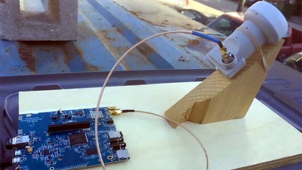
Where their achievement becomes especially interesting though is in their choice of receiver. We are all used to Ku-band receivers, you may even have one on your house somewhere for satellite TV. It will probably involve a parabolic dish with a narrow beam width and an LNB whose horn antenna is placed at its focus. It would have required some skill and effort to set up, because it has to be pointed very carefully at the satellite’s position in the sky. Outernet’s mission of delivering an information service with the lowest possible barrier to entry precludes the extra expense of shipping a dish and providing trained staff to align it, so they take a very different approach. Their receiver uses either an LNB horn or a small patch antenna pointing at the satellite, with none of the dishes or phased arrays you might be used to in a Ku-band installation.

You might wonder how such a receiver could possibly work with such a meagre antenna, but the secret lies in LoRa’s relatively tiny bandwidth as well as the resistance to co-channel interference that is a built-in feature of the LoRa modulation scheme. Even though the receiver will be illuminated by multiple satellites at once it is able to retrieve the signal and achieve a 30 kb/s data rate that they hope with technical refinements to increase to 100 kb/s. This rate will be enough over which to push an SD video stream to name just one of the several examples of the type of content they hope to deliver.

It’s likely that the average Hackaday reader will not be hiring satellite uplink time upon which to place their LoRa traffic. But this story does provide a demonstration of LoRa’s impressive capabilities, and will make us look upon our humble LNBs with new eyes.

Via ABOpen.

An Especially Tiny And Perfectly Formed FM Bug

It used to be something of an electronic rite of passage, the construction of an FM bug. Many of us will have taken a single RF transistor and a tiny coil of stiff wire, and with the help of a few passive components made an oscillator somewhere in the FM broadcast band. Connect up a microphone and you were a broadcaster, a prankster, and probably set upon a course towards a life in electronics. Back in the day such a bug might have been made from components robbed from a piece of scrap consumer gear such as a TV or VCR, and perhaps constructed spider-web style on a bit of tinplate. It wouldn’t have been stable and it certainly wouldn’t have been legal in many countries but the sense of achievement was huge.

As you might expect with a few decades of technological advancement, the science of FM bugs has moved with the times. Though you can still buy the single transistor bugs as kits there is a whole range of fancy chips designed for MP3 players that provide stable miniature transmitters with useful features such as stereo encoders. That’s not to say there isn’t scope for an updated simple bug too though, and here [James] delivers the goods with his tiny FM transmitter.

Gone is the transistor, and in its place is a MAX2606 voltage-controlled oscillator. The on-chip varicap and buffer provided by this device alleviate some of the stability issues suffered by the transistor circuits, and to improve performance further he’s added an AP2210 low-dropout regulator to catch any power-related drift. If it were ours we’d put in some kind of output network to use both sides of the differential output, but his single-ended solution at least offers simplicity. The whole is put on a board so tiny as to be dwarfed by a CR2032 cell, and we can see that a bug that size could provide hours of fun.

This may be a small and simple project, but it has found its way here for being an extremely well-executed one. It’s by no means the first FM bug we’ve shown you here, just a few are this one using scavenged SMD cellphone parts, or this more traditional circuit built on a piece of stripboard.

Deconstructing A Simple Op-Amp

Maybe you are familiar with the op-amp as an extremely versatile component, and you know how to quickly construct a huge variety of circuits with one. Maybe you even have a favorite op-amp or two for different applications, covering many possible niches. Standard circuits such as an inverting amplifier are your bread and butter, and the formula gain=-Rf/Ri is tattooed on your forearm.

But you can know how to use op-amps without really knowing how they work. Have you ever peered under the hood of an op-amp to find out what’s going on in there? Would you like to? Let’s take a simple device and examine it, piece by piece.

Continue reading “Deconstructing A Simple Op-Amp”

Scan Your Film The 3D Printed Way

Everyone has a box or two at home somewhere full of family photographs and slides from decades past. That holiday with Uncle Joe in Florida perhaps, or an unwelcome reminder of 1987’s Christmas jumper. It’s fair to say that some memories deserve to be left to gather dust, but what about the others in a world of digital images?

You could of course buy a film scanner to digitize Uncle Joe on the beach, but aside from the dubious quality of so many of them where’s the fun in that? Instead, how about 3D printing one? That’s what [Alexander Gee] did, in the form of an adapter to fit the lens mount of his Sony camera that contains both a 50mm enlarger lens and a mount for the slide. It’s a simple enough print, but he’s made enough parts parametric for users to be able to adjust it to their own camera’s mount.

Sometimes builds do not have to be complex, push boundaries, or contain more computing power than took us to the Moon. This one is simple and well-executed, and for anyone prepared to experiment could deliver results with a variety of cameras and lenses. Of course, you have to have some film to scan before you can use it, so perhaps you’d like to try a bit of home developing.