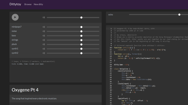
Dittytoy recreation of Jean-Michel Jarre's Oxygene Part IV

Generative Music Created In Minimalistic Javascript Code

Dittytoy user [srtuss] has recreated one of the most influential works of electronic music in an elegant nineteen kilobytes of Javascript code. The recreation of Jean-Michel Jarre’s Oxygene Part IV on the Dittytoy platform, currently in beta, plays live right in your browser. Dittytoy empowers users to create generative music online using a simple Javascript API. Syntax of the API is loosely based on that of Sonic Pi, a code-based music creation and performance tool.

“Oxygene (Part IV)” was recorded by Jean-Michel Jarre in 1976. It was Jarre’s most successful single, charted on the top ten in several countries, and was more recently featured in the Grand Theft Auto IV video game. In the 1990s, famed electronic music innovator Brian Eno used the term “generative music” to describe music generated by an electronic system comprising ever-changing elements that may be algorithmic or random.

Recreation of Jarre’s work required modeling the Korg Minipops 7 drum machine, one of the instruments presented in our slew of open-source synthesizers.

KiCad 2022 Year End Recap

KiCad 2022 End-of-Year Recap And 7.0 Preview

[Chris Gammell] moderated the KiCad 2022 End-of-Year Recap with several KiCad developers and librarians. They reviewed what’s been bubbling up in the nightly KiCad 6 builds, what we can expect from KiCad 7, and even answered some questions from the user community. Over the course of 2022, the KiCad project has grown both its development team and library team. The project even has a preliminary support commitment from the CERN Drawing Office!

Improvements to the KiCad Schematic Editor include smart wire dragging that simplifies moving components around within schematic diagrams. Components selected in the schematic now remain selected while switching to the PCB Editor. Internal documentation of schematics has advanced with support for fonts, embedded graphics, and the inclusion of hypertext links to datasheets and other reference materials. New features for PDF generation offer interactive files and links between sheets.

A new search panel within the KiCad PCB Editor supports finding components by footprint, net, or text search. A property panel allows common properties to be edited across multiple selected items. While a full-blown auto-router remains outside of the scope for KiCad, “push and shove” routing is faster and easier. An “attempt to finish” feature routes a quick connection for the currently selected trace, and “pack and move” positions all selected footprints into proximity to simplify placing them as neighbors within the board layout.

The KiCad PCB Editor also adds support for the use of fonts and inverted “knockout text” which even works on copper zones. Bitmap graphics can be imported and scaled beneath layout work as reference illustrations. Private footprint layers can be used to place extra documentation within footprints. The design rule checker (DRC) now can catch more layout issues, especially those that may impact manufacturability.

These are just a sampling of the impressive improvements we can expect with KiCad 7.0. There are also additions to circuit simulation and modeling features, a new command line interface for script-based automation, ARM64 support for KiCad running on Apple silicon, and a huge number of additions to the default library including symbols, footprints, and 3D Viewer models.

The KiCad team suggests several ways to support the project. There are always needs for additional developers and librarians. Financial contributions can be made at kicad.org. As users, we can run the nightly builds, try to break them, and give feedback in the form of detailed bug reports. Community testing will help make KiCad 7.0 as solid as possible. The project team is also seeking open hardware projects to include with KiCad 7.0 as demos.  For example, the StickHub project was included with KiCad 6.0 as a demo.

The official release of KiCad 7.0 is currently scheduled for January 31, 2023. While we wait, let’s flashback to our January 2022 presentation of what features made it into the KiCad 6.0 release.

Continue reading “KiCad 2022 End-of-Year Recap And 7.0 Preview”

Giant Spinning POV Christmas Tree

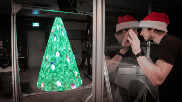
Spinning Holographic POV Christmas Tree Of Death

[Sean Hodgins] really harnessed the holiday spirit to create his very own Giant Spinning Holographic Christmas Tree (of Death). It’s a three-dimensional persistence-of-vision (POV) masterpiece, but as a collection of rapidly spinning metal elements, it’s potentially quite dangerous as well. As [Sean] demonstrates, the system can display other images and animations well beyond the realm of mere holiday trees.

Initial experiments focused on refining the mechanical structure, bearings, and motor. A 1/2 horsepower A.C. motor was selected and then the dimensions of the tree were “trimmed” to optimize a triangular frame that could be rotated at the necessary POV speed by the beefy motor.  A six-wire electrical slip ring allows power and control signaling to be coupled to the tree through its spinning central shaft.

The RGB elements are SK9888 LEDs also know as DotStar LEDs. DotStar LEDs are series-chainable, individually-addressable RGB LEDs similar to NeoPixels. However, with around 50 times the pulse width modulation (PWM) rate, DotStars are more suitable for POV applications than NeoPixels.  The LED chain is driven by a Raspberry Pi 4 single board computer using a clever system for storing image frames.

If deadly rotational velocity is not your cup of tea, consider this slower spinning RGB Christmas tree featuring a DIY slip ring. Or for more POV, may we suggest this minimalist persistence-of-vision display requiring only a few LEDs and an ATtiny CPU.

Continue reading “Spinning Holographic POV Christmas Tree Of Death”

DC Zia 30-in-ONE Badge for DEF CON 30

Nostalgic 30-in-ONE Electronics Badge For DEF CON 30

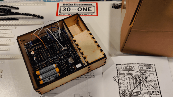
[hamster] and the DC Zia crew offered up a throwback 30-in-ONE Learn Electronics indie badge for DEF CON 30. The badge is inspired by the Radio Shack “100-in-1” style project kits that so many of us cut our teeth on back in the 70s and 80s.

DC Zia is a hacker group loosely associated with New Mexico who have been working together to make an indie badge for DEF CON each year.  If you aren’t familiar with the badgelife community of hardware hackers and programmers who make electronic indie conference badges, check out our BadgeLife Documentary.

The 30-in-ONE badge is provided in the form of a kit, so the learning and fun begins with assembling the badge. From there, an included booklet guides the badge holder through building and experimenting with 30 different circuits.

The included components include resistors, capacitors, LEDs, transistors, switches, transformer, speaker, OLED display, battery box, and a bundle of jumper wires for making any desired circuit connections.  The documented circuits have compelling titles such as the Electric Cat, Light Theremin, Grandfather Clock, and Frequency Counter.

Flashback to what DC Zia, and other groups, were up to five years prior in our expose on The Hardware Badges of DEF CON 25.

Continue reading “Nostalgic 30-in-ONE Electronics Badge For DEF CON 30”

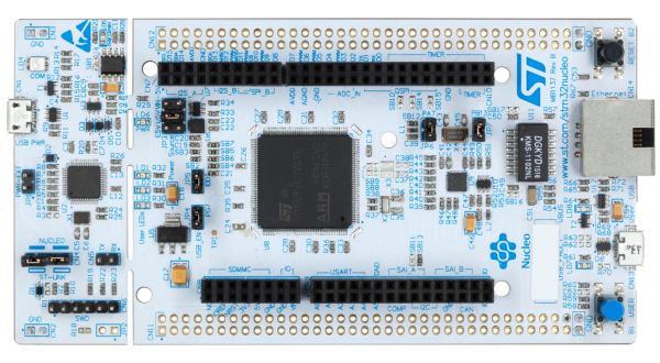
Nucleo-F429ZI development board with STM32F429 microcontroller

Epic Guide To Bare-Metal STM32 Programming

[Sergey Lyubka] put together this epic guide for bare-metal microcontroller programming.  While the general concepts should be applicable to most any microcontroller, [Sergey]s examples specifically relate to the Nucleo-F429ZI development board featuring the ARM-based STM32F429 microcontroller.

In the realm of computer systems, bare-metal programming most often refers to programming the processor without an intervening operating system. This generally applies to programming BIOS, hardware drivers, communication drivers, elements of the operating system, and so forth. Even in the world of embedded programming, were things are generally quite low-level (close to the metal), we’ve grown accustomed to a good amount of hardware abstraction. For example, we often start projects already standing on the shoulders of various libraries, boot loaders, and integrated development tools.

When we forego these abstractions and program directly on the microprocessor or microcontroller, we’re working on the bare metal. [Sergey] aptly defines this as programming the microcontroller “using just a compiler and a datasheet, nothing else.” His guide starts at the very foundation by examining the processor’s memory map and registers including locations for memory mapped I/O pins and other peripherals.

The guide walks us through writing up a minimal firmware program from boot vector to blinking an LED connected to an I/O pin. The demonstration continues with setup and use of necessary tools such as the compiler, linker, and flasher. We move on to increasingly advanced topics like timers, interrupts, UART output, debuggers, and even configuring an embedded web server to expose a complete device dashboard.

While initially more time consuming, working close to the metal provides a good deal of additional insight into, and control over, hardware operations.  For even more on the subject, you may like our STM32 Bootcamp series on bare-metal STM32 programming.

tiny surface mount seven segment display

Nano-Sized 7-Segment LED Display On A Surface Mount Module

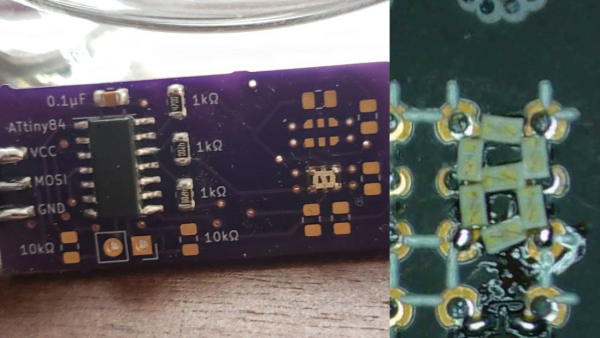
Inspired by a prank tweet, [Sam Ettinger] endeavored to create an SMD seven-segment display.  The NanoRaptor NanoSegment implements a panel of seven-segment display modules sized at “0806” each or just a bit wider than a standard 0805 SMD footprint.  Each of the seven segments is a single 0201 LED.  Six I/O lines and three resistors are required to operate each module.

To demonstrate the operation of his tiny display modules, Sam also created the “6Pin 7Seg” development board featuring an ATtiny84 microcontroller coupled to PCB footprints sized to receive the NanoRaptor NanoSegment display modules.  A demonstration of the board counts through digits displayed on one of the tiny seven-segment modules.

Hoping to reduce the module’s interface to two pins, Sam is now experimenting with a seven-segment display on a flex PCB that folds up into a 1208 footprint.  He is attempting to fold the resistors and a ATtiny20 microcontroller into an “origami PCB” configuration.

If these hacks are getting a little too small for your tastes, we’ve got you covered with this giant seven-segment display.


AI simulated drone flight track

Human Vs. AI Drone Racing At The University Of Zurich

[Thomas Bitmatta] and two other champion drone pilots visited the Robotics and Perception Group at the University of Zurich. The human pilots accepting the challenge to race drones against Artificial Intelligence “pilots” from the UZH research group.

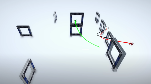
The human pilots took on two different types of AI challengers. The first type leverages 36 tracking cameras positioned above the flight arena. Each camera captures 400 frames per second of video. The AI-piloted drone is fitted with at least four tracking markers that can be identified in the captured video frames. The captured video is fed into a computer vision and navigation system that analyzes the video to compute flight commands. The flight commands are then transmitted to the drone over the same wireless control channel that would be used by a human pilot’s remote controller.

The second type of AI pilot utilizes an onboard camera and autonomous machine vision processing. The “vision drone” is designed to leverage visual perception from the camera with little or no assistance from external computational power.

Ultimately, the human pilots were victorious over both types AI pilots. The AI systems do not (yet) robustly accommodate unexpected deviation from optimal conditions. Small variations in operating conditions often lead to mistakes and fatal crashes for the AI pilots.

Both of the AI pilot systems utilize some of the latest research in machine learning and neural networking to learn how to fly a given track. The systems train for a track using a combination of simulated environments and real-world flight deployments. In their final hours together, the university research team invited the human pilots to set up a new course for a final race. In less than two hours, the AI system trained to fly the new course. In the resulting real-world flight of the AI drone, its performance was quite impressive and shows great promise for the future of autonomous flight. We’re betting on the bots before long.

Continue reading “Human Vs. AI Drone Racing At The University Of Zurich”