An analog multimeter being used as a ping display

Classic Multimeter Tells You If Your WiFi’s Working

Debugging network issues isn’t easy; many a sysadmin has spent hours trying to figure out which of the many links between client and server is misbehaving. Having a few clear pointers helps: if you can show that the internet connection is up, that already narrows down the problem to either the server or, most likely, the client computer.

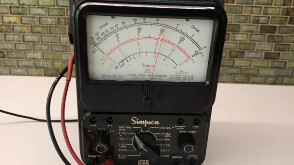
After hearing “is the internet up” one too many times, [whiskeytangohotel] decided to make a clearly visible indicator to show the status of the local uplink. He used his father’s old Simpson 260 VOM as a display, with its large analog indicator pointing at a steady value if the internet’s up, and wagging back and forth if there’s an outage. The exact value indicated is determined by the average ping time for a couple of different servers, so that you can also tell if the connection is slower than normal.

The ping times are measured by an ESP8266 connected to WiFi, which checks a predefined list of web servers and calculates the average ping time every fifteen seconds. An analog value in the 2.5 V range is then generated and measured by the meter. The smooth motion of an old analog meter stands in nice contrast to the modern-day problem of unstable WiFi.

While analog multimeters definitely have their uses, we’re the first to admit that our classic meters don’t see as much action as they could. Repurposing them as [whiskeytangohotel] did is a neat way of keeping those heirlooms around for the next generation. Of course, if you don’t have an analog multimeter, you could also use an analog clock for your ping meter. Continue reading “Classic Multimeter Tells You If Your WiFi’s Working”

A doorblell made from a stepper motor and a hard drive

Minimalistic Doorbell Doesn’t Need An Internet Connection – Or Even A Power Supply

Doorbells are among those everyday objects that started out simple but picked up an immense amount of complexity over the years. What began as a mechanism to bang two pieces of metal together evolved into all kinds of wired and wireless electric bells, finally culminating in today’s smart doorbells that beam a live video feed to their owners even if they’re half a world away.

But sometimes, less is more. [Low tech obsession] built a doorbell out of spare components that doesn’t require Internet connectivity or even a power supply. But it’s not a purely mechanical device either: the visitor turns a knob mounted on a stepper motor, generating pulses of alternating current. These pulses are then fed into the voice coil of an old hard drive, causing its arm to vibrate and strike a bell, mounted where the platters used to be.

Besides being a great piece of minimalistic design, the doorbell is also a neat demonstration of Faraday’s law of induction. The stepper motor is apparently robust enough to withstand vandalism, although we can imagine that the doorbell’s odd shape might confuse some well-meaning visitors too. If you’re into unusual doorbells, you might want to check out this one made from an old wall phone, as well as this electromechanical contraption.

Continue reading “Minimalistic Doorbell Doesn’t Need An Internet Connection – Or Even A Power Supply”

An RF remote control with a LoRa receiver next to it

Reverse Engineering A 900 MHz RC Transmitter And Receiver

For those building their own remote controlled devices like RC boats and quadcopter drones, having a good transmitter-receiver setup is a significant factor in the eventual usability of their build. Many transmitters are available in the 2.4 GHz band, but some operate at different frequencies, like the 868/915 MHz band. The TBS Crossfire is one such transmitter, and it’s become a popular model thanks to its long-range performance.

The channel hopping sequence of a TBS Crossfire transmitter
The channel hopping sequence

When [g3gg0] bought a Crossfire set for his drone, he discovered that the receiver module consisted of not much more than a PIC32 microcontroller and an SX1272 LoRa modem. This led him to ponder if the RF protocol would be easy to decode. As it turns out, it was not trivial, but not impossible either. First, he built his own SPI sniffer using a CYC1000 FPGA board to reveal the exact register settings that the PIC32 sent to the SX1272. The Crossfire uses channel hopping, and by simply looking at the register settings it was easy to figure out the hopping sequence.

Once that was out of the way, the next step was to figure out what data was flowing through those channels. The data packets appeared to be built up in a straightforward way, but they included an unknown CRC checksum. Luckily, brute-forcing it was not hard; the checksum is most likely used to keep receivers from picking up signals that come from a different transmitter than their own.

[g3gg0]’s blog post goes into intricate detail on both the Crossfire’s protocol as well as the reverse engineering process needed to obtain this information. The eventual conclusion is that while the protocol is efficient and robust, it provides no security against eavesdropping or deliberate interference. Of course, that’s perfectly fine for most RC applications, as long as the user is aware of this fact.

If you’re into decoding RF protocols, you might also want to try using a logic analyzer. But if you merely want to replicate an existing transmitter’s signals, it might be easier to simply spoof a few button presses.

Continue reading “Reverse Engineering A 900 MHz RC Transmitter And Receiver”

The inside of a Laser-Induced Breakdown Spectrometer

Spectrometer Detects Chemicals By Zapping Samples With A Laser Beam

Here at Hackaday, we love projects that result in useful lab equipment for a fraction of the cost of professional gear. [Lorenz], over at Advanced Tinkering, built his own instrument for Laser-Induced Breakdown Spectroscopy, or LIBS, and it’s quite an impressive device. LIBS is a technique for analyzing substances to find their chemical composition. Basically, the idea is to zap a sample with a powerful laser, then look at the little cloud of plasma that results and measure the wavelengths emitted by it.

A plot showing the spectrum of hematite
The spectrum of hematite (iron oxide), compared to that of pure iron

The laser [Lorenz] used is a Nd:YAG unit salvaged from a tattoo removal machine. After it fires a pulse, a photodiode detects the light and triggers a spectrometer, which consists of a diffraction grating, a few lenses and mirrors, and a linear CCD sensor. The grating splits the incoming lights into its constituent components, which fall onto the CCD and trigger its pixels. An STM32 Nucleo board reads out the results and sends them to a PC for further processing.

That processing bit turned out to be a full project on its own. [Lorenz] called upon [g3gg0], who software that simplifies the operation of the spectrometer. First, it helps with the instrument’s calibration. Point the detector at a well-known light source like a laser or a fluorescent lamp, then select the expected wavelengths on the resulting spectral plot. The software then automatically calculates the correct coefficients to map each pixel to a specific wavelength.

The software also contains a database of spectra corresponding to chemical elements: once you’ve taken a spectrum of an unknown sample, you can overlay these onto the resulting plot and try to find a match. The resulting system seems to work quite well. Samples of iron oxide and silver oxide gave a reasonable match to their constituent components.

We’ve seen other types of spectrometers before: if you simply want to characterize a light source, check out this Raspberry Pi-based model. If you’re interested in chemical analysis you might also want to look at this open-source Raman spectrometer.

Continue reading “Spectrometer Detects Chemicals By Zapping Samples With A Laser Beam”

A handheld printer printing "CHI 2022 and a capacitor symbol

Print-a-Sketch Turns Any Surface Into A Printed Circuit Board

Although powerful design software and cheap manufacturing services have made rolling your own PCBs easier than ever, there are some situations where a piece of FR-4 just doesn’t cut it: think art projects with hidden LEDs or biomedical applications that need to attach to the human body. For such occasions, [Narjes Pourjafarian] and her team at Saarland University in Germany developed Print-a-Sketch: a handheld device that lets you print electric circuits on almost any surface using conductive ink.  Also check out their academic paper (PDF).

The heart of the device is a piezoelectric print head, as used in some types of inkjet printer. It dispenses tiny droplets of silver nanoparticle ink, which is conductive enough to make useful electronic circuits by simply printing a schematic. Lines can be drawn to connect components, while customized footprints can hold LEDs, capacitors or even integrated circuits.

As demonstrated in the video embedded below, the Print-a-Sketch can be used in various different modes. In freehand mode, you can draw whatever you like just by moving the device around. But it also has several assisted sketching modes, where it can straighten out wobbly lines, draw multiple lines in parallel, or even print complete predefined shapes. Especially satisfying is the way it can draw resistors by literally printing zig-zagging lines.

Thanks to an optical motion sensor, similar to the ones used in gaming mice, the device knows at all times where it is and how fast it’s going. That enables the control circuitry to compensate for unsteady movement; the authors claim a printing precision of less than 0.5 mm. In addition, an RGB camera is used to detect the material underneath and adjust the amount of ink dispensed, depending on how absorbent the surface is: rough paper needs more ink to obtain a conductive trace than a ceramic tile.

The number of potential applications seems limitless: how about a yoga mat with integrated touch buttons to control the video player on your iPad? A piece of kinesiology tape with an integrated stretch sensor to measure the exact motion of your arm? Or a floor tile with a printed moisture sensor? All of these are demonstrated by the team, but we’re sure our readers can come up with many more ideas.

Of course, drawing circuits using conductive ink is not a new idea: previous projects either relied on drawing the entire thing by hand, or used traditional inkjet printers. But the Print-a-Sketch’s sophisticated hardware and software really put it in a league of its own. And since the entire design is open-source, you can simply build one and bring your ideas to life.

Continue reading “Print-a-Sketch Turns Any Surface Into A Printed Circuit Board”

Sergiy Nesterenko giving his Remoticon 2021 talk

Remoticon 2021 // Sergiy Nesterenko Keeps Hardware Running Through Lightning And Cosmic Rays

Getting to space is hard enough. You have to go up a few hundred miles, then go sideways really fast to enter orbit. But getting something into space is one thing: keeping a delicate instrument working as it travels there is quite another. In his talk at Remoticon 2021, [Sergiy Nesterenko], former Radiation Effects Engineer at SpaceX, walks us through all the things that can destroy your sensitive electronics on the way up.

The trouble already starts way before liftoff. Due to an accident of geography, several launch sites are located in areas prone to severe thunderstorms: not the ideal location to put a 300-foot long metal tube upright and leave it standing for a day. Other hazards near the launch pad include wayward wildlife and salty spray from the ocean.

Those dangers are gone once you’re in space, but then suddenly heat becomes a problem: if your spacecraft is sitting in full sunlight, it will quickly heat up to 135 °C, while the parts in the shade cool off to -150 °C. A simple solution is to spin your craft along its axis to ensure an even heat load on all sides, similar to the way you rotate sausages on your barbecue.

But one of the most challenging problems facing electronics in space is radiation. [Sergiy] explains in detail the various types of radiation that a spacecraft might encounter: charged particles in the Van Allen belts, cosmic rays once you get away from Low Earth orbit, and a variety of ionized junk ejected from the Sun every now and then. The easiest way to reduce the radiation load on your electronics is simply to stay near Earth and take cover within its magnetic field.

For interplanetary spacecraft there’s no escaping the onslaught, and the only to survive is to make your electronics “rad-hard”. Shielding is generally not an option because of weight constraints, so engineers make use of components that have been tested in radiation chambers to ensure they will not suddenly short-circuit. Adding redundant circuits as well as self-monitoring features like watchdog timers also helps to make flight computers more robust.

[Sergiy]’s talk is full of interesting anecdotes that will delight the inner astronaut in all of us. Ever imagined a bat trying to hitch a ride on a Space Shuttle? As it turns out, one aspiring space bat did just that. And while designing space-qualified electronics is not something most of us do every day, [Sergiy]’s experiences provide plenty of tips for more down-to-earth problems. After all, salt and moisture will eat away cables on your bicycle just as they do on a moon rocket.

Be sure to also check out the links embedded in the talk’s slides for lots of great background information.

Continue reading “Remoticon 2021 // Sergiy Nesterenko Keeps Hardware Running Through Lightning And Cosmic Rays”

A USB interface connected to a Psion Organiser II

Arduino Nano Adds USB Interface To The Psion Organiser II

Introduced in 1984, the Psion Organiser series defined the first generation of electronic organizers or PDAs (personal digital assistants). Even though these devices are now over 30 years old, the Psion Organiser scene is alive and well: with new hardware and software is still being developed by enthusiasts the world over.

A USB interface connected to a Psion Organiser II
The Organiser II, with its brand-new USB interface

One of those enthusiasts is [James Stanley], who designed and built a USB interface for the Psion Organiser II. Although a “CommsLink” module providing an RS-232 port was available back in the day, it’s become hard to find, inspiring [James] to design a completely new module based on an Arduino Nano. Hooking it up to the Psion’s data bus was a simple matter of wiring up the eight data lines to the Nano’s GPIO ports. A set of series resistors served to prevent bus contention without having to add glue logic.

Getting the software working was a bit more difficult: the Organiser’s native OPL programming language doesn’t allow the user to directly access the expansion port’s memory address, so [James] had to write a routine in HD6303 machine code to perform the read, then call that routine from OPL to display the result on the screen. Currently, the routine only supports reading data from the Arduino, but extending it to a bidirectional interface should be possible too.

Finally, [James] designed and 3D printed a neat enclosure for the Arduino-USB interface, which makes it look almost as sleek as the original CommsLink module. Perhaps with a bit of further development, this could turn into another way to connect old Psions to the internet. We’ve also featured a new type of Datapak to enhance the Organiser’s memory. Continue reading “Arduino Nano Adds USB Interface To The Psion Organiser II”