Intel C4004

Inventing The Microprocessor: The Intel 4004

We recently looked at the origins of the integrated circuit (IC) and the calculator, which was the IC’s first killer app, but a surprise twist is that the calculator played a big part in the invention of the next world-changing marvel, the microprocessor.

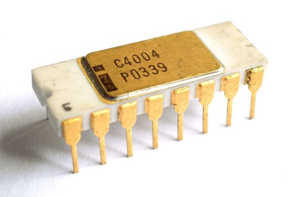
There is some dispute as to which company invented the microprocessor, and we’ll talk about that further down. But who invented the first commercially available microprocessor? That honor goes to Intel for the 4004.

Path To The 4004

Busicom calculator motherboard based on 4004 (center) and the calculator (right)

We pick up the tale with Robert Noyce, who had co-invented the IC while at Fairchild Semiconductor. In July 1968 he left Fairchild to co-found Intel for the purpose of manufacturing semiconductor memory chips.

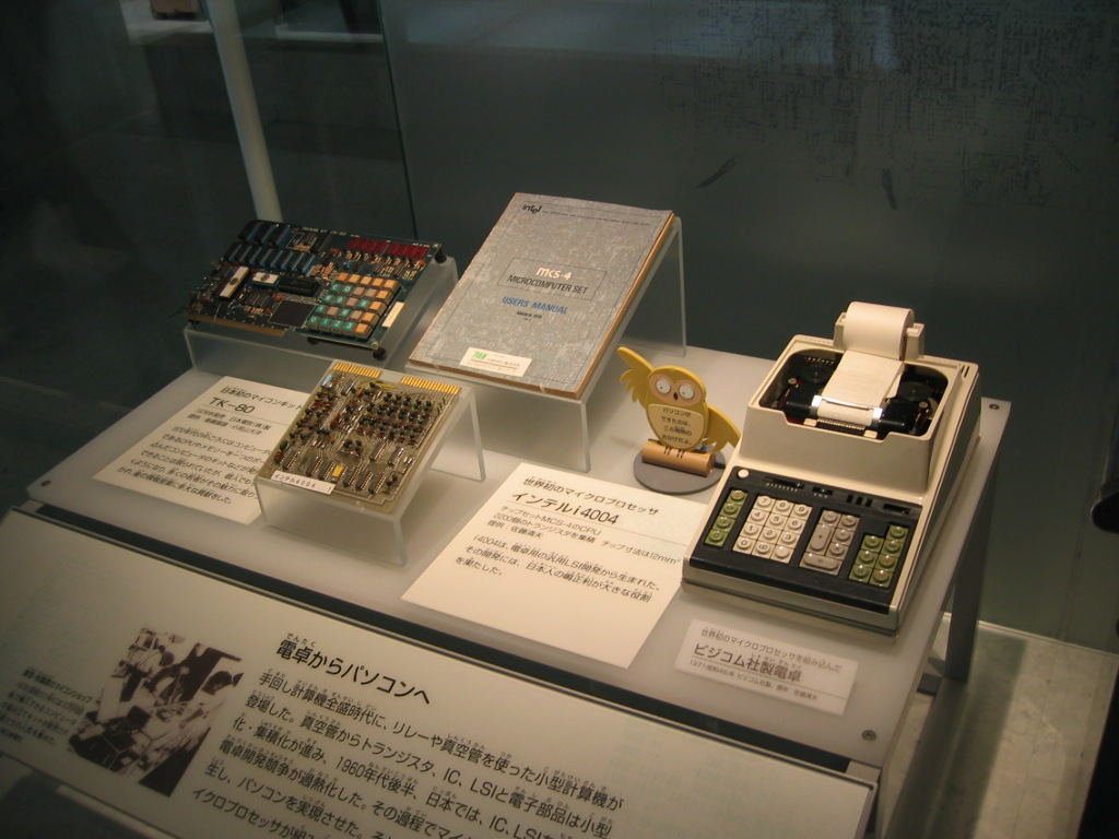
While Intel was still a new startup living off of their initial $3 million in financing, and before they had a semiconductor memory product, as many start-ups do to survive they took on custom work. In April 1969, Japanese company Busicom hired them to do LSI (Large-Scale Integration) work for a family of calculators.

Busicom’s design, consisting of twelve interlinked chips, was considered a complicated one. For example, it included shift-register memory, a serial type of memory which complicates the control logic. It also used Binary Coded Decimal (BCD) arithmetic. Marcian Edward Hoff Jr — known as “Ted”, head of the Intel’s Application Research Department, felt that the design was even more complicated than a general purpose computer like the PDP-8, which had a fairly simple architecture. He felt they may not be able to meet the cost targets and so Noyce gave Hoff the go-ahead to look for ways to simplify it.

Continue reading “Inventing The Microprocessor: The Intel 4004”

Smooth stepper motor robot arm

Stepper Motor Robot Arm Has Smooth Moves

[Tobias Kuhn] had watched a YouTube video about a robot arm which used servo motors, and wanted to try making one himself. But he found it hard to get slow or smooth movements out of the servos. Even removing the microcontroller and trying to work with the servo’s driver-IC and potentiometer from an Arduino Nano didn’t get him satisfaction.

Then he found the very affordable 28BYJ-48 stepper motor. After some experimenting, he came up with a smooth moving robot arm with four steppers controlled from an Arduino Mega and A4988 stepper motor drivers. Rather than write a bunch of stepper motor code himself, he installed and ran a four-axis fork of grbl on the Arduino, turning it into a stepper motor controller. One minor hitch was that the A4988 motor drivers are for bipolar stepper motors but 28BYJ-48 steppers are unipolar. Luckily he knew of a very simple hack which our [Brian Benchoff] wrote about for turning a unipolar motor into a bipolar motor.

To tell the robot arm what to do, he built a replica arm with potentiometers in place of the stepper motors. As he manipulates the replica, the values of the potentiometers are read by a Raspberry Pi and some custom Python code which sends the appropriate G-code to the Arduino/grbl controlled robot arm. There’s a bit of a lag but when he moves the replica arm, the robot arm does the same move. See it in action in the video below.

Continue reading “Stepper Motor Robot Arm Has Smooth Moves”

Neural Networking: Robots Learning From Video

Humans are very good at watching others and imitating what they do. Show someone a video of flipping a switch to turn on a CNC machine and after a single viewing they’ll be able to do it themselves. But can a robot do the same?

Bear in mind that we want the demonstration video to be of a human arm and hand flipping the switch. When the robot does it, the camera that is its eye will be seeing its robot arm and gripper. So somehow it’ll have to know that its robot parts are equivalent to the human parts in the demonstration video. Oh, and the switch in the demonstration video may be a different model and make, and the CNC machine may be a different one, though we’ll at least put the robot within reach of its switch.

Sound difficult?

Researchers from Google Brain and the University of Southern California have done it. In their paper describing how, they talk about a few different experiments but we’ll focus on just one, getting a robot to imitate pouring a liquid from a container into a cup.

Continue reading “Neural Networking: Robots Learning From Video”

Weather matrix lamp

Pi Weather Lamp Puts Lava Lamps To Shame

Representing the weather on an LED lamp in a manner that’s easy to interpret can be difficult, but [Gosse Adema]’s weather/matrix lamp makes it not only obvious what the weather is but also offers a very attractive display. For rain, drops of light move downward, and for wind, sideways. The temperature is shown using a range of colors from red to blue, and since he is situated in the Netherlands he needed snow, which he shows as white. A rainy, windy day has lights moving both down and sideways with temperature information as the background.

Weather matrix lamp

To implement it he mounted LED strips inside a 3D printed cylinder with reflectors for each LED, all of which fitted into a glass cylinder taken from another lamp purchased online. The brains of it is a Raspberry Pi Zero W housed in the bottom along with a fan. Both the LEDs and the fan are controlled by the Pi. He took a lot of care with power management, first calculating the current that the LEDs would draw, and then writing Python code to limit that draw. However upon measurement, the current draw was much lower than expected and so he resized the power supply appropriately. He also took care to correctly size the wires and properly distribute the power with a specially made power distribution board. Overall, we really like the thorough job he’s done.

But then again, what’s not to like about [Gosse]’s projects. In the area of lighting, he’s dazzled us with WiFi controlled Christmas tree ornaments, but he’s also delighted us with a Prusa i3 based LEGO 3D printer on which he printed LEGO parts and then made a special extruder for printing chocolate.

Edgytokei

Edgytokei’s Incredible Mechanism Shows Time Without A Face

Taking inspiration from Japanese nunchucks, [ekaggrat singh kalsi] came up with a brilliant clock that tells time using only hour and minute hands, and of course a base for them to sit on. The hands at certain parts of the hour seem to float in the air, or as he puts it, to sit on their edges, hence the name, the Edgytokei, translating as “edge clock”.

The time is a little difficult to read at first unless you’ve drawn in a clock face with numbers as we’ve done here. 9:02 and 9:54 are simple enough, but 9:20 and 9:33 can be difficult to translate into a time at first glance. Since both hands have to be the same length for the mechanism to work, how do you tell the two hands apart? [ekaggrat] included a ring of LEDs in the hub at the base and another at the end of one of the hands. Whichever ring of LEDs is turned on, indicates the tip of the minute hand. But the best way to get an idea of how it works is to watch it action in the video below.

We have to admire the simplicity and cleanliness of his implementation. The elbow and the hub at the base each hide a stepper motor with attached gear. Gear tracks lining the interior of the hands’ interact with the motor gears to move the hands. And to keep things clean, power is transferred using copper tape lining the exteriors.

On the Hackaday.io page [ekaggrat] talks about how difficult it was to come up with the algorithms and especially the code for homing the hands to the 12:00 position, given that homing can be initiated while the hands can be in any orientation. The hand positions are encoded in G-code, and a borrowed G-code parser running on an Arduino Nano in the base controls it all.

Continue reading “Edgytokei’s Incredible Mechanism Shows Time Without A Face”

GhettoLED boombox with LED strips lighting up speakers

This Boombox Hack Is Lit

Old boomboxes make great hacks. Their design is iconic; yes they look dated but that really just builds on the nostalgic urge to have one hanging around. Plus their big cases simply invite adding things inside in a way impossible with contemporary electronics.

[Danc0rp] hacked his JVC M70 boombox to make the speakers glow with animated light, bumping VU meters, and a pulsing horizontal bar above the tape deck. The effect is superb. The cones of the speakers act like a projection surface and the grilles hide the LEDs until they activate, and enhance the effects once unleashed. It is one of the best LED speaker hacks we’ve ever seen.

Custom board with Arduino UNO

The light effects are provided by LED strips, which for the speakers are attached just inside the outer rim. The brains behind it all is an Arduino UNO. To connect to it, he soldered components to a blank Arduino prototyping board. That board takes input from the boombox’s line-out and does some filtering (an attempt to address some ground noise) before passing the signal on to the Arduino. That board also interfaces between the Arduino and the LED strips. The schematic is available on his GitHub page. He’d like to replace the board with a custom PCB instead and is looking for design help.

The result is not only beautiful but professional looking too. This makes us wonder why boomboxes don’t come this way. See it for yourself in the video below.

Continue reading “This Boombox Hack Is Lit”

Barbara McClintock: Against The Genetic Grain

The tale of much of Barbara McClintock’s life is that of the scientist working long hours with a microscope seeking to solve mysteries. The mystery she spent most of her career trying to solve was how all cells in an organism can contain the same DNA, and yet divide to produce cells serving different functions; basically how cells differentiate. And for that, she got a Nobel prize all to herself, which is no small feat either.

Becoming a Scientist

Human chromosomes, long strands of DNA
Human chromosomes, long strands of DNA by Steffen Dietzel CC BY-SA 3.0

McClintock was born on June 16, 1902, in Hartford, Connecticut, USA. From age three until beginning school, she lived with her aunt in Brooklyn, New York while her father strove financially to start up a medical practice. She was a solitary and independent-minded child, a trait she later called her “capacity to be alone”.

In 1919, she began her studies at Cornell’s College of Agriculture and took her first course in genetics in 1921. A year later, due to the interest she showed in genetics, she was invited to take the graduate genetics course at Cornell. It was here that she became interested in the new field of cytogenetics, specifically of maize or corn. Cytogenetics studies how the chromosomes relate to cell behavior, particularly during cell division. Chromosomes are the long strands of DNA within the nucleus of every cell and shown here in the photo at a time when they are condensed, or coiled up.

While still at Cornell she developed a number of methods for visualizing and characterizing maize which ended up in textbooks. She also became the first to describe the morphology of the ten maize chromosomes, basically their form and structural relationships, which then allowed her to discover more about the chromosomes. One of her colleagues observed that ten of the seventeen significant advances made in the field at Cornell between 1929 and 1935 were hers. This was only the first step in what would be the remarkable career of a very well respected scientist.

Continue reading “Barbara McClintock: Against The Genetic Grain”