The Flight That Made The Calculator And Changed The World

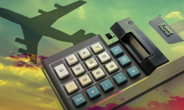
It was the fall of 1965 and Jack Kilby and Patrick Haggerty of Texas Instruments sat on a flight as Haggerty explained his idea for a calculator that could fit in the palm of a hand. This was a huge challenge since at that time calculators were the size of typewriters and plugged into wall sockets for their power. Kilby, who’d co-invented the integrated circuit just seven years earlier while at TI, lived to solve problems.

Fig. 2 from US 3,819,921 Miniature electronic calculator

By the time they landed, Kilby had decided they should come up with a calculator that could fit in your pocket, cost less than $100, and could add, subtract, multiply, divide and maybe do square roots. He chose the code name, Project Cal Tech, for this endeavor, which seemed logical as TI had previously had a Project MIT.

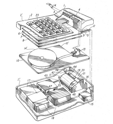
Rather than study how existing calculators worked, they decided to start from scratch. The task was broken into five parts: the keyboard, the memory, the processor, the power supply, and some form of output. The processing portion came down to a four-chip design, one more than was initially hoped for. The output was also tricky for the time. CRTs were out of the question, neon lights required too high a voltage and LEDs were still not bright enough. In the end, they developed a thermal printer that burned images into heat-sensitive paper.

Just over twelve months later, with the parts all spread out on a table, it quietly spat out correct answers. A patent application was filed resulting in US patent 3,819,921, Miniature electronic calculator, which outlined the basic design for all the calculators to follow. This, idea borne of a discussion on an airplane, was a pivotal moment that changed the way we teach every student, and brought the power of solid-state computing technology into everyday life.

Continue reading “The Flight That Made The Calculator And Changed The World”

CosmicWatch muon detector

Make A Cheap Muon Detector Using Cosmicwatch

A little over a year ago we’d written about a sub $100 muon detector that MIT doctoral candidate [Spencer Axani] and a few others had put together. At the time there was little more than a paper on arxiv.org about it. Now, a few versions later they’ve refined it to the level of a kit with full instructions for making your own under the banner, CosmicWatch including PCB Gerber files for the two surface mount boards you’ll need to assemble.

What’s a muon? The Earth is under constant bombardment from cosmic rays, most of them being nuclei expelled from supernova explosions. As they collide with nuclei in our atmosphere, pions and kaons are produced, and the pions then decay into muons.  These muons are similar to electrons, having a +1 or -1 charge, but with 200 times the mass.

This pion-to-muon decay happens higher than 10 km above the Earth’s surface. But the muons have a lifetime at rest of 2.2 μs. This means that the number of muons peak at around 10 km and decrease as you go down. A jetliner at 30,000 feet will encounter far more muons than will someone at the Earth’s surface where there’s one per cm2 per minute, and the deeper underground you go the fewer still. This makes them useful for inferring altitude and depth.

How does CosmicWatch detect these muons? The working components of the detector consist of a plastic scintillator, a silicon photomultiplier (SiPM), a main circuit board which does signal amplification and peak detection among other things, and an Arduino nano.

As a muon passes through the scintillating material, some of its energy is absorbed and re-emitted as photons. Those photons are detected by the silicon photomultiplier (SiPM) which then outputs an electrical signal that is approximately 0.5 μs wide and 10-100 mV. That’s then amplified by a factor of 6. However, the amplified pulse is too brief for the Arduino nano and so it’s stretched out by the peak detector to roughly 100 μs. The Arduino samples the peak detector’s output and calculates the original pulse’s amplitude.

Their webpage has copious details on where to get the parts, the software and how to make it. However, they do assume you can either find a cheap photomultiplier somewhere or buy it in quantities of over 100 brand new, presumably as part of a school program. That bulk purchase makes the difference between a $50 part and one just over $100. But being skilled hackers we’re sure you can find other ways to save costs, and $150 for a muon detector still isn’t too unreasonable.

Detecting muons seems to have become a thing lately. Not too long ago we reported on a Hackaday prize entry for a detector that uses Russian Geiger–Müller Tubes.

TensorFlow Lite demos

Smarter Phones In Your Hacks With TensorFlow Lite

One way to run a compute-intensive neural network on a hack has been to put a decent laptop onboard. But wouldn’t it be great if you could go smaller and cheaper by using a phone instead? If your neural network was written using Google’s TensorFlow framework then you’ve had the option of using TensorFlow Mobile, but it doesn’t use any of the phone’s accelerated hardware, and so it might not have been fast enough.

TensorFlow Lite architecture

Google has just released a new solution, the developer preview of TensofFlow Lite for iOS and Android and announced plans to support Raspberry Pi 3. On Android, the bottom layer is the Android Neural Networks API which makes use of the phone’s DSP, GPU and/or any other specialized hardware to speed up computations. Failing that, it falls back on the CPU.

Currently, fewer operators are supported than with TensforFlor Mobile, but more will be added. (Most of what you do in TensorFlow is done through operators, or ops. See our introduction to TensorFlow article if you need a refresher on how TensorFlow works.) The Lite version is intended to be the successor to Mobile. As with Mobile, you’d only do inference on the device. That means you’d train the neural network elsewhere, perhaps on a GPU-rich desktop or on a GPU farm over the network, and then make use of the trained network on your device.

What are we envisioning here? How about replacing the MacBook Pro on the self-driving RC cars we’ve talked about with a much smaller, lighter and less power-hungry Android phone? The phone even has a camera and an IMU built-in, though you’d need a way to talk to the rest of the hardware in lieu of GPIO.

You can try out TensorFlow Lite fairly easily by going to their GitHub and downloading a pre-built binary. We suspect that’s what was done to produce the first of the demonstration videos below.

Continue reading “Smarter Phones In Your Hacks With TensorFlow Lite”

Prototyping, Making A Board For, And Coding An ARM Neural Net Robot

[Sean Hodgins]’s calls his three-part video series an Arduino Neural Network Robot but we’d rather call it an enjoyable series on prototyping, designing a board with surface mount parts, assembling it, and oh yeah, putting a neural network on it, all the while offering plenty of useful tips.

In part one, prototype and design, he starts us out with a prototype using a breadboard. The final robot isn’t on an Arduino, but instead is on a custom-made board built around an ARM Cortex-M0+ processor. However, for the prototype, he uses a SparkFun SAM21 Arduino-sized board, a Pololu DRV8835 dual motor driver board, four photoresistors, two motors, a battery, and sundry other parts.

Once he’s proven the prototype works, he creates the schematic for his custom board. Rather than start from scratch, he goes to SparkFun’s and Pololu’s websites for the schematics of their boards and incorporates those into his design. From there he talks about how and why he starts out in a CAD program, then moves on to KiCad where he talks about his approach to layout.

Part two is about soldering and assembly, from how he sorts the components while still in their shipping packages, to tips on doing the reflow in a toaster oven, and fixing bridges and parts that aren’t on all their pads, including the microprocessor.

In Part three he writes the code. The robot’s objective is simple, run away from the light. He first tests the photoresistors without the motors and then writes a procedural program to make the robot afraid of the light, this time with the motors. Finally, he writes the neural network code, but not before first giving a decent explanation of how the neural network works. He admits that you don’t really need a neural network to make the robot run away from the light. But from his comparisons of the robot running using the procedural approach and then the neural network approach, we think the neural network one responds better to what would be the in-between cases for the procedural approach. Admittedly, it could be that a better procedural version could be written, but having the neural network saved him the trouble and he’s shown us a lot that can be reused from the effort.

In case you want to replicate this, [Sean]’s provided a GitHub page with BOM, code and so on. Check out all three parts below, or watch just the parts that interest you.

Continue reading “Prototyping, Making A Board For, And Coding An ARM Neural Net Robot”

Mega Game & Watch Octopus

Mega Game & Watch: True Multiplayer Game

Today we’re used to handheld game consoles like the Nintendo Switch, that let you roam around in 3D worlds which include not only 3D players but more terrain than many people walk around in real life in a week. But back in the early 1980s Nintendo’s handheld offering was the Game & Watch, which used a segmented LCD display. An entire segment could be used to represent the player, with player segments spread throughout the display. To move the player, the previous player segment would be turned off while another adjacent one would be on. That also meant that a console could play only one game. Despite these limitations they were very popular for their time.

[Thomas Tilley] decided to improve on the old Game & Watch in a different way, by making it bigger, much bigger. So big in fact that even many teenage players can’t reach both the button to move left and the button to move right in time, turning it into a highly co-operative two-player game. Judging by the video below, that made playing it double the fun. The game he chose to tackle is the Game & Watch Octopus, or Mysteries of the Sea and Mysteries of the Deep in the UK.

Continue reading “Mega Game & Watch: True Multiplayer Game”

Industrial 42" multitouch pc

Hacking An Industrial 42″ Multitouch PC

We’re slowly moving in the direction where everyone will have a touch screen desk like in the 1982 TRON movie or in the 1987 Star Trek: The Next Generation series with its ubiquitous touchscreen starship controls. [FFcossag] lucked into that future when a local company offered him an industrial 42″ multitouch PC that they were throwing out. A few hacks later and he has us all suitably envious.

Before hacking away though, he had to take care of some magic smoke. The source of this turned out to be yellow goop on the PC’s power supply that had turned conductive across a resistor. Cleaning it fixed the problem.

Moving on to the hacks, he added brightness control by using a potentiometer to control the power to the backlight. Be sure to watch carefully in the video below where he’s attaching a magnet and cord to the potentiometer, and encasing it all in epoxy. At that point, we’re pretty sure we see him spin up a hard drive platter with a sandpaper disk attached to it, forming a bench top disc sander and making us like this hack even more.

He also replaced a small speaker with a larger speaker and amplifier, giving a volume and sound quality difference that’s like night and day. He also added a breakout board with relays for power management, eliminating a seven watt continuous draw when in standby mode.

Be sure to watch the video to the end where he leaves us with a tour of the hacked interior hardware. We like how he’s labeled all his handiwork for any future hacker who might open it up

Continue reading “Hacking An Industrial 42″ Multitouch PC”

Maria Goeppert-Mayer: The Other Nobel Prize Winner

Maria Goeppert-Mayer was one of only two women to win the Nobel prize for physics thus far, the other being Marie Curie. And yet her name isn’t anywhere near as well known as Marie Curie’s. She also worked on the Manhattan Project and spent time during her long career with Enrico Fermi, Max Born, Edward Teller, and many other physics luminaries.

She was “other” in another way too. She followed her husband from university to university, and due to prevailing rules against hiring both husband and wife, often had to take a non-faculty position, sometimes even with no salary. Yet being the other, or plus-one, seemed to give her what every pure scientist desires, the freedom to explore. And explore she did, widely. She was always on the cutting edge, and all the time working with the leading luminaries of physics. For a scientist, her story reads like it’s too good to be true, which is what makes it so delightful to read about.

Continue reading “Maria Goeppert-Mayer: The Other Nobel Prize Winner”