New PCB Revives Ancient Bubble LED Displays

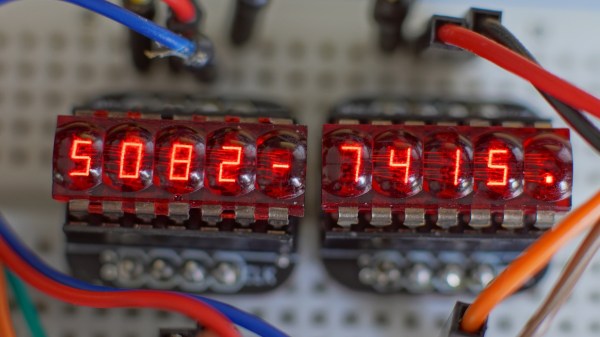
For those of us who remember LED calculators, the HP 5082-7400 series red “bubble” displays hold a special charm. Available in 3, 4, or 5-digit varieties, these multiplexed 7-segment displays provided countless hours of entertainment to those who would spell upside-down words on their pocket calculators. In case you happen to be lucky enough to have access to a few of these beautiful vintage display sticks, [Gigawipf] has designed a small driver PCB that lets you easily interface them to a modern microcontroller.

At the heart of the board, aimed at either the 5082-7405 or 5082-7415 5-digit modules, are a pair of 74HC595 shift registers in tiny QFN packages. Five lines from one register drive one of the common cathodes for the selected digit, while the other register drives the eight anode lines through 330-Ohm resistors. The boards are slightly smaller than the width of the displays allowing you to stack them seamlessly for more digits, and eight header pins on each allow you to plug them into solderless breadboards for prototyping. The result is easy to drive with some simple code, and [Gigawipf] provides an example for Arduino as part of the project. The Eagle design files are supplied, as well as Gerbers for those who just want to have some boards made. This sounds like a great way to get some of these vintage displays going again.

If you can’t find any of these displays to play, with, you can try making some larger digits from individual surface-mount LEDs.

Running Linux On A Thermostat

When your thermostat comes with Linux running on it, that’s not a hack. When it doesn’t, and you get Linux on there yourself, it most definitely is. This is exactly what [cz7asm] has done. In a recent video, he shows the Honeywell thermostat booting Linux and running a wide range of software.

While the hardware inside the thermostat doesn’t afford all the luxuries of a typical modern embedded Linux, it’s got enough room for the basics. The system runs from a 1 MB rootfs in RAM, and has a 2.5 MB kernel image, leaving a spare 12 MB for everything else. With just these meager resources, [cz7asm] shows how the system can use a USB network adapter, connecting to telehack.com for some command-line retro fun, and host a web server, although no browser runs yet. There’s also framebuffer support for displaying graphics and animations, and the usual Linux terminal goodness.

All we’ve seen so far is the video, so we hope [cz7asm] posts the code somewhere, because we’re tired of using our thermostat just to run the AC.

You might remember [cz7asm] from his previous thermostatic triumph: running Doom. Check out the video of the latest thermostat adventure after the break.

Thanks to [Piecutter] for the tip!

Continue reading “Running Linux On A Thermostat”

Simple Trick For LEDs On Solderless Breadboards

Sometimes the most useful hacks are also the simplest ones. A case in point is the LED and resistor assembly that [Skippy] recently posted on his blog. The idea is to solder up some pre-made indicators with integrated resistors to save space on the breadboard when prototyping — instead of four slots, you only use two per LED. This is about as easy a trick as you can imagine, but it has the hallmark of a classic hack: a high utility-to-work ratio.

The deluxe assembly uses a two-pin header as a base to plug into the breadboard. This, of course, could be optional since some breadboards have a memory for the widest pin previously inserted — using header pins may eventually make the slots a little flaky for smaller component leads. But, if you’re mostly using header pins in the breadboard anyway, this is a good way to avoid kinking the leads.

While there are LEDs available with integrated dropping resistors, building your own means you can use whatever LEDs you prefer — or simply have on hand — and adjust the resistor value for different voltages or to adjust the brightness. And for those of you who plug in LEDs without current-limiting resistors, we’re going to assume that you’ve thoroughly researched whatever is driving them and done the math to ensure they’re safe. Or not: they’re your LEDs after all.

We previously featured a no-solder breadboarding trick for SMD LEDs. What’s your favorite solderless breadboard hack? Let us know in the comments below.

Thanks to [Roboteernat] for the tip!

Protect Yourself — And Your Project — While Working With Mains Power

When debugging ordinary low-voltage circuitry, you’re pretty safe: unless you have some really power-hungry devices that need a ton of current, there aren’t that many truly bad things that can happen, so you can take a lot of liberties with electrical-safety rules. With mains-powered devices, you don’t have this luxury, and a lack of knowledge, sloppy work practices, or simple mistakes can cost you — and your project — dearly. While you still need to know what you’re doing and use the requisite caution, [Yann Guidon]’s latest project — and entry in the 2019 Hackaday Prize —  a mains protection box, might keep simple mistakes from becoming a disaster.

There are a number of precautions you can take when working with mains power. We’ve all used the simple in-line power strip so you can quickly switch off the current, but [Yann] has included a number of devices that can be configured in different ways to experiment with mains-powered devices safely. Built into a sturdy open-topped wooden box with carry handles, the project evokes the traditional breadboard in appearance and functionality. A number of different devices are included, which could be re-configured into different topologies if needed.

[Yann] included an isolation transformer, which can be useful not only for protection against shock in case of accidentally grounding, but also for noise suppression. There is also a variac, which allows the output voltage to be adjusted over a wide range for testing. Of course, circuit breakers are a must, and current and voltage meters keep you informed about what’s going on. A big, easy-to-access switch cuts the power quickly when needed.

The (maybe) final touch is an adjustable output current limit, which is still a work in progress. Built around a current-monitoring relay and a DPDT relay wired as a latch, this allows the output to be disconnected if it draws more than a specified current, equivalent to between 10 W and 100 W. This is the perfect thing for initial testing of new projects.

So, if you’re thinking of working on mains-powered projects, have a close look at what [Yann] has assembled, and learn proper safety procedures before you begin. One place to start is with a great series by our own Jenny List about mains safety: part one and part two. Stay safe out there!

GlScopeClient: A Permissively-Licensed Remote Oscilloscope Utility

One of the most convenient things about modern digital oscilloscopes is that you can access the recorded data on a computer for later analysis, advanced protocol debugging, or simply the convenience of remote capture. The problem is that the software isn’t always ideal. Vendor-supplied utilities are typically closed-source and they try to nickel-and-dime you for every a-la-carte protocol and/or feature. The open-source options come with their own issues, from performance-limiting designs, to incomplete features, to license constraints. Faced with these issues, [Andrew Zonenberg] decided to take matters into his own hands and create glscopeclient, a permissively-licensed open-source remote oscilloscope utility.

The eventual goal is to allow you to do remotely anything you would normally do using the scope’s front panel, plus capture and analyze data on the computer side. The code uses a modular architecture that allows for various backends to talk to different scopes. At the moment, the only backend fully implemented is for LeCroy scopes, although this is enough to demonstrate the power of the idea. The obvious “gl” in the name gives away the secret — the code uses OpenGL for rendering, which allows for some very fancy graphics at high frame rates.

Behind the slick look, however, are some serious debugging tools. Protocol analyzers include USB, UART, JTAG, eye pattern analysis, plus FFT-based spectra with waterfall displays. The code is in GitHub, and most of the announcements and discussion seem to happen on [Andrew]’s twitter account, which you can follow @azonenberg. It’s a work-in-progress, but a serious one, and something we’re going to keep our eyes on.

You can check out a video of the program after the break.

Now, if you want to literally talk to your oscilloscope, we covered that, too.

Continue reading “GlScopeClient: A Permissively-Licensed Remote Oscilloscope Utility”

Fun With Negative Resistance II: Unobtanium Russian Tunnel Diodes

In the first part of this series, we took a look at a “toy” negative-differential-resistance circuit made from two ordinary transistors. Although this circuit allows experimentation with negative-resistance devices without the need to source rare parts, its performance is severely limited. This is not the case for actual tunnel diodes, which exploit quantum tunneling effects to create a negative differential resistance characteristic. While these two-terminal devices once ruled the fastest electronic designs, their use has fallen off dramatically with the rise of other technologies. As a result, the average electronics hacker probably has never encountered one. That ends today.

Due to the efficiencies of the modern on-line marketplace, these rare beasts of the diode world are not completely unobtainable. Although new-production diodes are difficult for individuals to get their hands on, a wide range of surplus tunnel diodes can still be found on eBay for as little as $1 each in lots of ten. While you’d be better off with any number of modern technologies for new designs, exploring the properties of these odd devices can be an interesting learning experience.

For this installment, I dug deep into my collection of semiconductor exotica for some Russian 3И306M gallium arsenide tunnel diodes that I purchased a few years ago. Let’s have a look at what you can do with just a diode — if it’s the right kind, that is.

[Note: the images are all small in the article; click them to get a full-sized version]

Continue reading “Fun With Negative Resistance II: Unobtanium Russian Tunnel Diodes”

Examine Source Code To Assembly Mapping With PenguinTrace

C-programmers who don’t have a mental model of what’s going on underneath their thin veneer of abstraction above assembly code are destined for trouble. In order to provide a convenient way to understand what C-code gets compiled to and how it runs on the machine, [Alex Beharrell] has created penguinTrace, a program which allows you to see what instructions your code compiles to, and examine how it executes.

While you can get somewhat similar functionality out of standard debuggers, penguinTrace was purpose-built to facilitate exploration of how the whole process works. You can single-step through the instructions your code compiled to, examine variables, and look at the stack — the usual debugger stuff — but structured more for exploration and learning than full-on debugging. Based on our experiences when we learned low-level programming, anything that can help novices build that all-important mental picture of what’s going on underneath is a good thing. But, since it was written with a secondary purpose of learning how debuggers themselves work, it’s a great opportunity for exploring that space, too.

The UI harnesses CodeMirror to provide a browser-based interface, and is configurable to use Clang or GCC for compilation. It supports AMD64/X86-64 and AArch64 architectures, and will run on Windows using WSL: if you’ve got a PC running Linux, a Raspberry Pi, or a Windows box, you’re good to go. The code is AGPL-licensed and available on GitHub. So, if you want to gain a better understanding of what happens when you compile and run “hello, world,” grab a copy and start exploring.

This isn’t the only way to debug, though – we previously featured an application that allows a type of debugging for the Arduino platform.