We know, we know. Despite being called ESP32-Plane-Radar, this project from [Mateusz Juszczyk] isn’t actually using radar. But thanks to the round LCD this desktop gadget does a fantastic job of recreating a classic radar display, and by pulling in Automatic Dependent Surveillance–Broadcast (ADS-B) data, the visuals even match nearby real-world aircraft.
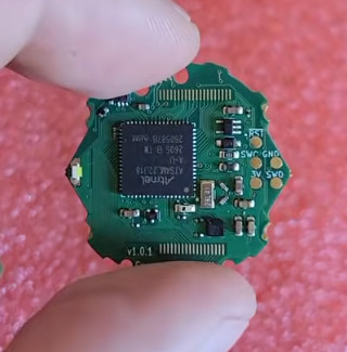
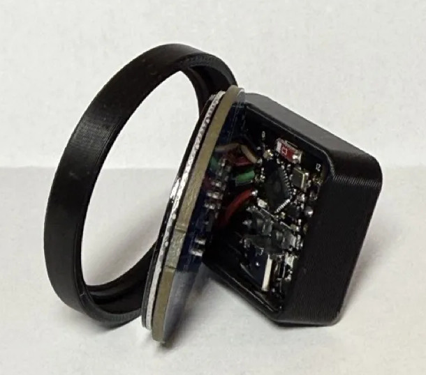 Perhaps the best part of this project is just how easy it is for others to get in on the action. Although the presentation certainly looks professional — and expensive, if we’re being honest — there’s nothing particularly exotic going on here. Specifically, there’s ESP32-C3 Super Mini behind the scenes cranking through the ADS-B data and pushing it out to a circular GC9A01 display. A minimalistic 3D printed enclosure holds both components, and while it’s undeniably slick as-is, we can’t help but think there’s potential here for more elaborate designs.
As you probably guessed from the lack of a radio in the parts list, the code [Mateusz] provides doesn’t actually sniff ADS-B out of the air. It connects to the local network over WiFi, and then hits adsb.fi to pull in crowdsourced flight data. Since the device has to connect to the network anyway, the code also offers up a web-based configuration interface which puts a little more polish on what’s already an impressive presentation.
We used a round GC9A01 display on the Vectorscope back in 2023, so if anyone ports this over to their old Supercon badge we’d love to see it in action.
Thanks to [Mauricio] for the tip.