
The blower and a smaller motor than what's actually driving it.

Electric Snowblower Clears The Way With Hobby Parts

If you live in snow country and own a home, you either have a snowblower or wish you did. The alternatives are either an expensive and potentially unreliable plow service, or back-breaking (and heart-attack inducing) shoveling. [RCLifeOn] was one of those people in the second category, until he decided to do something about it: electrifying a scrap snowblower with a blown engine. 

The usual brushless DC motors and electronic speed controllers [RCLifeOn] has on hand to get his R/C life on with don’t quite have enough oomph to handle both functions of a snowblower. For those of you cursed to live in warmer climes, the modern snowblower is both self-propelled via its twin wheels, and generally has a two-stage powered snow-removal “blower” consisting of an auger to break up the snow and an impeller to blast it out of the machine and many meters off the driveway. On the traditional gas-powered models, these are both powered via belts off the same motor, but that wasn’t going to work.

He kept the belts, and simply used a pair of motors, each with their own ESCs that are controlled via oversized thumb wheels on the handles. The belts couple to the motors with 3D printed pulleys. Belt tension is achieved in the case of the wheels through a simple and sensible shimming arrangement. In the case of the blower motor, he uses a 3D printed adjustable mount to get the appropriate tension. To help it hold long-term (given the issues with creep in 3D prints) he’s got a bearing on a second mount opposite the motor.  It holds up for his demo, which consists of clearing a driveway of 10cm of snow and then plowing through a pile larger than the mouth of the machine. In other words: it works.

The build, as unfortunately common on YouTube, is shy on specific details– but in this case that’s fine. Even if he’d open-sourced everything and posted STEP or STL files, it wouldn’t save much time since you’d pretty well have to re-engineer the build to fit your own snowblower, if you were so inclined. As with many hacks of this nature, the point of sharing it is to show how easy it is and provide the inspiration. As the cartoons used to say, “knowing is half the battle.”

If one was to re-implement this hack, we could not encourage you strongly enough to put in the standard dead-man’s switch, a feature commercial snowblowers share with things like lawnmowers. As annoying as it is to hang onto with frozen fingers, that safety feature is there for a reason.

If your driveway is short, you can save on gas and fuel costs with an extension cord. Or you could just stay inside and do the job by remote control, but that comes with its own pitfalls.

Continue reading “Electric Snowblower Clears The Way With Hobby Parts” →
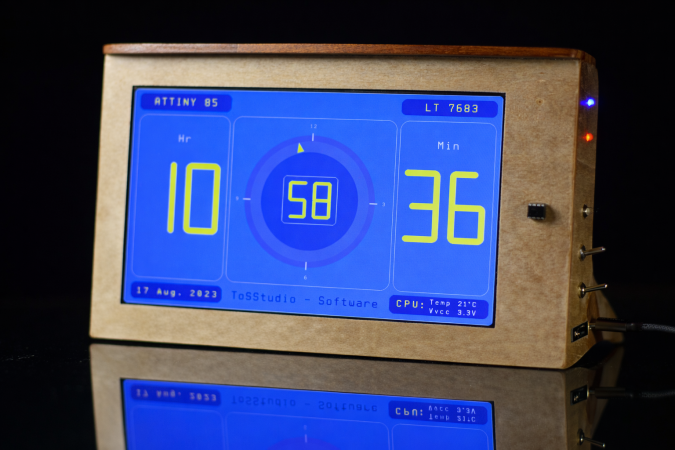
The clock demo on display

Drive 1024×600 Pixels Via I2C With An ATtiny85

If you need to drive a big screen for a project, it’s fair to say your first thought isn’t going to be to use the ATtiny85. With just 512 bytes of RAM and 8 kilobytes of flash memory, the 8-bit micro seems a little cramped to drive, say, a 10″ screen. Yet that’s exactly what [ToSStudio] is doing with TinyTFT_LT7683: 1024 x 600 pixels of TFT goodness, over I2C no less.

With the right TFT controller, this little micro-controller can do magic.

The name kind of gives away the secret: it won’t work on just any TFT display. It’s using properties of the LT7683 display driver, though if you don’t have one of those, the RA8875 is also compatible. Those drivers can take more than just a pixel stream– a good thing, since you’d be hard pressed to get that many pixels streaming from an ATtiny. These are character/graphic display drivers, which means you can get them to draw both characters and graphics on the screen if you speak the lingo.

It’s still not blazing fast; the documentation suggests “static or moderately dynamic UIs” as the suggested use case, and a clock is of the pre-programmed examples. From that, we can surmise that you can get 1 FPS or better with this code. You’re limited both by the simple micro-controller and the bandwidth of the I2C bus, but within those limits this seems like a very powerful technique.

This isn’t the first ATtiny graphics library to blow our minds, but if you really want an impressive graphics demo from the little micro that could, you really need to race the beam.

Thanks to [Thomas Scherer] for the tip!

The modified hot glue gun, reassembled

Tired Of Burnt Fingers? Try PID Tuning The Hot Glue Gun

Hot glue guns are pretty simple beasts: there’s an on/off switch, a heating element, and a source of current, be it battery or wired. You turn it on, and the heater starts warming up; eventually you can start extruding the thermoplastic sticks we call “hot glue”. Since there’s no temperature control, the longer you run the gun, the warmer it gets until it is inevitably hotter than you actually want– either burning you or oozing thermoplastic out the tip. [Mellow_Labs] was sick of that after a marathon hot-glue session, and decided to improve on his hot glue gun with PID tuning in the video embedded below.

PID tuning is probably a familiar concept to most of you, particularly those who have 3D printers, where it’s used in exactly the same way [Mellow_Labs] puts it to work in the hot glue gun.  By varying the input (in this case the power to the heater) proportional both to the Parameter (in this case, temperature) as well as the Integral and Derivative of that value, you can have a much steadier control than more naive algorithms, like the simple “on/off” thermostat that leads to large temperature swings.

In this case [Mellow_Labs] is implementing the PID control using a thermistor that looks like it came from a 3D printer, and a MOSFET driven by an RP2040. Microcontroller gets its power via the hot glue gun’s battery fed through a buck converter. Since he has them, a small OLED screen displays temperature, which is set with a pair of push-buttons. Thus, one can set a temperature hot enough to melt the glue, but low enough to avoid oozing or third degree burns.

He does not share the code he’s running on the RP2040, but if you are inspired to replicate this project and don’t want to roll your own, there are plenty of example PID scripts out there, like the one in this lovely robot. No, PID isn’t reserved for thermostats– but if you are controlling heat, it’s not reserved for electric, either. Some intrepid soul put built a PID controller for a charcoal BBQ once. Continue reading “Tired Of Burnt Fingers? Try PID Tuning The Hot Glue Gun” →

The clock and the rebuilt calculator from which its VFD was donated.

An RPN Calculator And A Bonus VFD Clock From Casio Revival

Have you heard the saying “the problem is the solution”? It seems to originate in the permaculture movement, but it can apply equally well to electronics. Take the problem [shiura] had: a Casio Mini CM-602 that had let out the magic smoke. The solution was a twofer: rebuild the Casio into a modern number cruncher with Reverse Polish Notation (RPN), and save the Vacuum Fluorescent Display (VFD) for a gorgeous WiFi clock.

[shiura]’s write-up includes a helpful guide for reverse engineering the pins on this sort of VFD, if you don’t happen to have the same model calculator (or VFD tube) they’re working with. If you’ve done this sort of thing, you know what to expect: power it up and kill power to the pins, one by one, to map out which segments or characters go out, thereby identifying the anodes and grid electrodes. The cathodes had already been ID’d from looking at the PCB. After that it’s just a matter of wiring the VFD to an ESP32 via a transistor array to get the voltages right, and voila! Clock. The code and case design files for this clock — including an editable .blend — are available via GitHub.

The calculator half of the project is an incredibly elegant hack that relies on the fact that the Casio’s CPU has the same pin pitch as modern micros: 2.54 mm, or 0.1″, so an RP2040 zero can sit in the footprint of the original CPU, scanning the keypads with its GPIO. Then an I2C display is separately wired up to replace the clockified VFD. Perhaps some driver circuitry for the VFD died, or [shiura] salvaged the display before deciding to save the calculator, because otherwise we see no reason why this brain transplant couldn’t be done while keeping the original display. Admittedly having two lines on the display instead of one make the “new” calculator a tad more usable. The code for that is also available on GitHub, and while the readme is in Japanese, machine translations have gotten pretty good and the code is quite readable on its own.

Longtime readers will likely be familiar with [shiura]’s work, with a number of finely crafted clocks having been featured from the Japanese maker, along with vintage pocket computer repairs. Bringing both together makes this twin hack particularly on-brand.

Continue reading “An RPN Calculator And A Bonus VFD Clock From Casio Revival” →

[Mark] shows off footage from a D1 master on the repaired deck

Reviving ReBoot With A Tape Deck Repair

Do you remember ReBoot? If you were into early CGI, the name probably rings a bell, since when it premiered in 1994 it was the first fully computer-animated show on TV. Some time ago, a group found a pile of tapes from Mainframe Studios in Canada, the people behind ReBoot, and the computer historians amongst us were very excited… until they turned out to be digital broadcast master tapes. Exciting for fans of lost media, sure, but not quite the LTO backups of Mainframe’s SGI workstations some of us had hoped would turn up. Still, [Mark Westhaver], [Bryan Baker] and others at the “ReBoot Rewind” project have made great strides, to the point that in their latest update video they declare “We Saved ReBoot”

What does it take to revive a 30-year-old television project? Well, as stated, they started with the tapes. These aren’t ordinary VHS tapes: the Sony D-1 tapes, which were also known by the moniker “4:2:2”, are a format that most people who didn’t work in the TV or film industry will have never seen, and the tape decks are rare as hen’s teeth these days. Just getting a working one, and keeping it working, was one of the biggest challenges [Mark] and Reboot Rewind faced. In the end it took three somewhat-dodgy machines long past their service lives and a miraculously located spare read/write head to get a stable scanning rate.

The uncompressed digital output of these tapes isn’t something you can just burn to a DVD, either. The 720 × 576 resolution video stream is captured raw, but there are minor editing tweaks that need to be made in addition to tape errors that have cropped up over the years, and those need to be dealt with before the video and audio data gets encoded into a modern format. The video briefly glosses [Bryan Baker]’s workflow to do just that. At least they aren’t stuck with terrible USB video capture dongles VHS lovers have to deal with. Even if you don’t care about ReBoot, this isn’t the only show that was archived on D1 tapes so that workflow might be of interest to media fans.

We covered ReBoot Rewind when they were first searching for tape decks, so it’s great to have an update. Alas, the rights holders haven’t yet decided how exactly they’re going to release this fine footage, so if like this author you have fond memories of ReBoot, you may have to wait a bit longer for a reWatch.

Continue reading “Reviving ReBoot With A Tape Deck Repair” →

Sleeping Rough In Alaska With A USPS Cargo Bike

Out of all 49 beautiful US states (plus New Jersey), the one you’d probably least want to camp outside in during the winter is arguably Alaska. If you were to spend a night camping out in the Alaskan winter, your first choice of shelter almost certainly wouldn’t be a USPS electric cargo trike, but over on YouTube [Matt Spears] shows that it’s not that hard to make a lovely little camper out of the mail bike. 

We’re not sure how much use these sorts of cargo trikes get in Alaska, but [Matt] seems to have acquired this one surplus after an entirely-predictable crash took one of the mirrors off. A delta configuration trike — single wheel in front — is tippy at the best of times, but the high center of gravity you’d get from a loading the rear with mail just makes it worse. That evidently did not deter the United States Postal Service, and it didn’t deter [Matt] either.

His conversion is rather minimal: to turn the cargo compartment into a camper, he only adds a few lights, a latch on the inside of the rear door, and a wood-burning stove for heat. Rather than have heavy insulation shrink the already-small cargo compartment, [Matt] opts to insulate himself with a pile of warm sleeping bags. Some zip-tie tire chains even let him get the bike moving (slowly) in a winter storm that he claims got his truck stuck.

While it might not be a practical winter vehicle, at least on un-plowed mountain roads, starting with an electric-assist cargo trike Uncle Sam already paid for represented a huge cost and time savings vs starting from scratch like this teardrop bike camper we featured a while back. While not as luxurious, it seems more practical for off-roading than another electric RV we’ve seen.

Continue reading “Sleeping Rough In Alaska With A USPS Cargo Bike” →

Pickle Diodes, Asymmetric Jacobs Ladders, And Other AC Surprises

While we’re 100 years past Edison’s fear, uncertainty, and doubt campaign, the fact of the matter is that DC is a bit easier to wrap one’s head around. It’s just so honest in its directness. AC, though? It can be a little shifty, and that results in some unexpected behaviors, as seen in this video from [The Action Lab].

He starts off with a very relatable observation: have you ever noticed that when you plug in a pickle, only half of it lights up? What’s up with that? Well, it’s related to the asymmetry he sees on his Jacobs ladder that has one side grow hotter than the other. In fact, it goes back to something welders who use DC know about well: the Debye sheath.

The arc of a welder, or a Jacobs ladder, or a pickle lamp is a plasma: ions and free electrons. Whichever electrode has negative is going to repel the plasma’s electrons, resulting in a sheath of positive charge around it. This positively-charged ions in the Debye sheath are going to accelerate into the anode, and voila! Heating. That’s why it matters which way the current goes when you’re welding.

With DC, that makes sense. In AC, well — one side starts as negatively charged, and that’s all it takes. It heats preferentially by creating a temporary Debye sheath. The hotter electrode is going to preferentially give off electrons compared to its colder twin — which amplifies the effect every time it swings back to negative. It seems like there’s no way to get a pure AC waveform across a plasma; there’s a positive feedback loop at whatever electrode starts negative that wants to introduce a DC bias. That’s most dramatically demonstrated with a pickle: it lights up on the preferentially heated side, showing the DC bias. Technically, that makes the infamous electric pickle a diode. We suspect the same thing would happen in a hot dog, which gives us the idea for the tastiest bridge rectifier. Nobody tell OSHA.

[The Action Lab] explains in more detail in his video, and demonstrates with ring-shaped electrode how geometry can introduce its own bias. For those of us who spend most of our time slinging solder in low-voltage DC applications, this sort of thing is fascinating.  It might be old hat to others here; if the science of a plain Jacobs ladder no longer excites you, maybe you’d find it more electrifying built into a blade.

Continue reading “Pickle Diodes, Asymmetric Jacobs Ladders, And Other AC Surprises” →