Valve has always designed hacker-friendly hardware, and in that spirit, [NaKyle Wright] released Inkterface, a design for an E-ink faceplate to fit the recently released Steam Machine. As far as projects go, this one is meticulously documented, so give it a peek.
The system uses a selection of components that include a 5.83″ E-ink panel and driver board, a small lithium-polymer battery, and an ESP32-based controller board. A cleverly-designed 3D printed frame and bezel hold everything just so, creating a snug assembly with minimal wiring hassles.
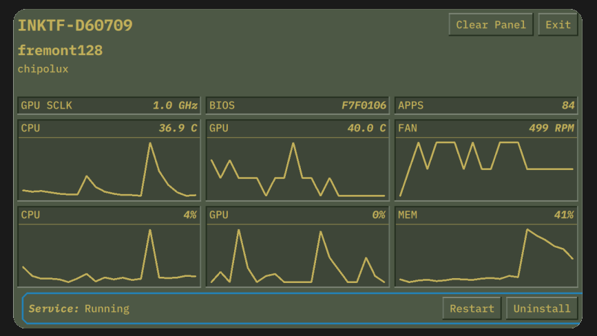
The faceplate is wireless and self-contained, attaching with the help of four magnets. On the software side, the host machine communicates over Bluetooth, and a service takes care of pushing updates. An app for configuring and talking to the display will be available on Steam eventually, but in the meantime one can install that part manually.
[NaKyle]’s bill of materials calls for specific components, but the underlying design is very modular. Should one wish to make hardware or component changes, alterations to the 3D printed parts might be needed as well. Fortunately, [NaKyle] includes the .step files alongside the .stl models. We love to see that, because it makes tweaking or customizing so much more accessible. A homebrewed version of this E-ink panel might be just the thing to complement a homebrewed Steam machine.
Be sure to also check out the repository of Steam hardware, which contains drawings and 3D models of the Steam Deck and Steam Controller, useful for designing holders or custom brackets or whatever else one may need.