It used to be that time was a lot more relative than it is today. With smartphones synced to GPS and network providers’ clocks, we all pretty much have access to an authoritative current time, giving few of us today the wiggle room to explain a tardy arrival at work to an impatient boss by saying our watch is running slow.
Even when that excuse was plausible, it was a bit weak, since almost every telephone system had some sort of time service. The correct time was but a phone call away, announced at first by live operators then later by machines called speaking clocks. Most of these services had been phased out long ago, but one, the speaking clock service in Australia, sounded for the last time at the end of September.
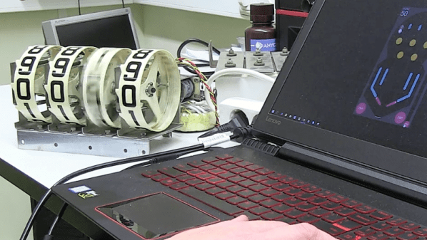
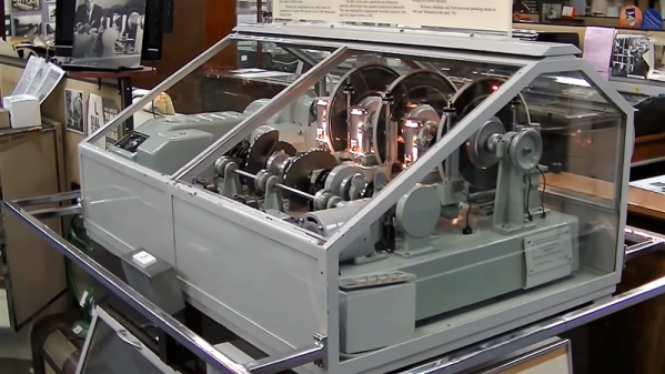
While the decommissioned machine was just another beige box living in a telco rack, the speaking clocks that preceded it were wonderfully complex electromechanical devices, and perfect fodder for a Retrotechtacular deep-dive. Here’s a look at the Australian speaking clock known as “George” and why speaking clocks were once the highest of technology.
Continue reading “Retrotechtacular: The Speaking Clock Goes Silent”