Airloom’s Whacky Wind Clothesline Turbine Idea

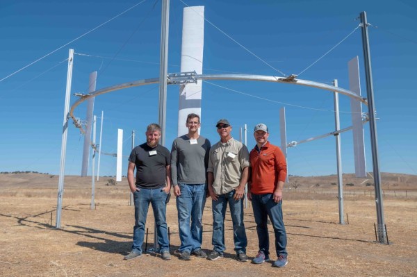
What if you don’t put airfoils on a central, spinning axis, but instead have them careen around a circular track? If you’re a company called Airloom, you’d say that it’s a very cheap, very efficient and highly desirable way to install wind-based generators that can do away with those unsightly and massive 100+ meter tall wind turbines, whether on- or offshore. Although grand claims are made, and venture capital firms have poured in some money, hard data is tough to find on their exact design, or the operating details of their one and only claimed kW-level prototype.

Transpower's 'flying clothesline' wind turbine setup.
Transpower’s ‘flying clothesline’ wind turbine setup.

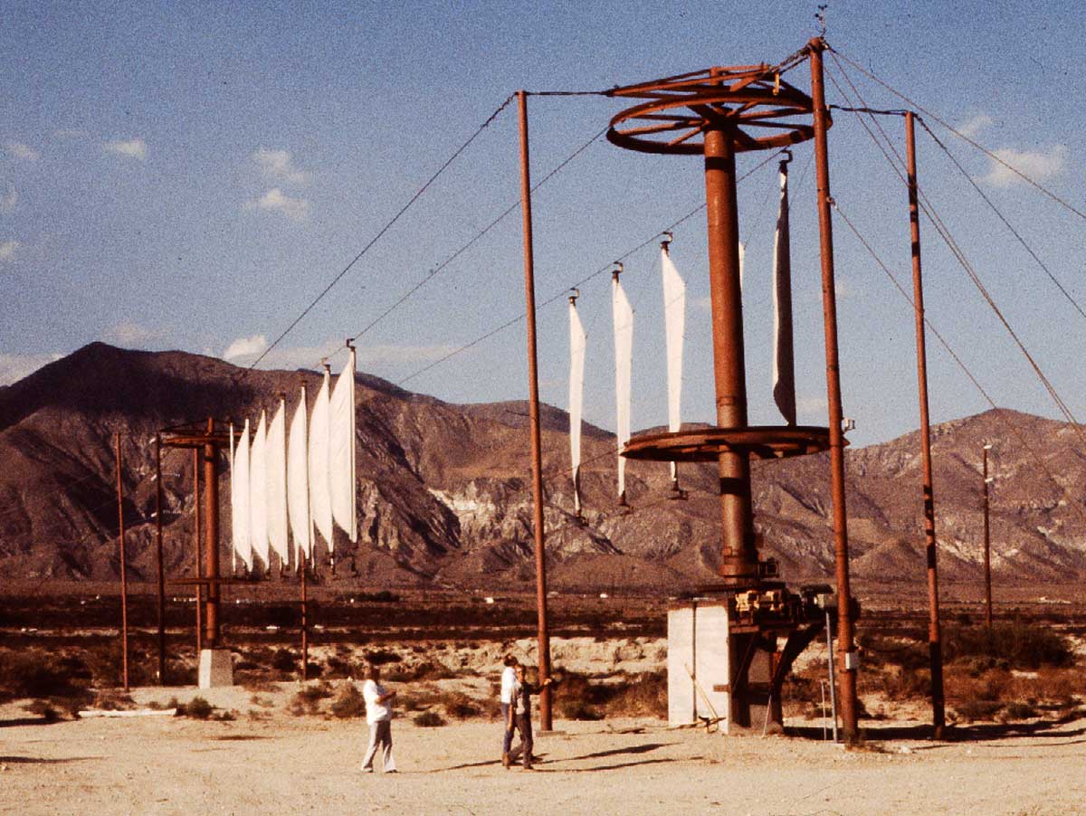
Despite the claims made by Airloom, they’re not the first to have this idea, with Transpower in the 1980s making itself famous with their ‘flying clothesline’ that featured a continuous loop of sails tensioned between two ropes. These ran around a pole on either end with each having a generator for a claimed total of 200 kW. Ultimately Transpower seems to have gone under along with many other wind power pioneers of the era as they couldn’t make their idea economically feasible. Something which is a definite trend in the field.

Some parts about Airloom’s design are definitely concerning, with the available images showing each airfoil running along a central rail on a number of wheels and with their ‘Power Takeoff’ (i.e. generator) not defined in any meaningful manner. Here is where [Robert Murray-Smith] had a bit of fun in a recent video, creating his own dual-chain version that somewhat resembles a mixture between the Transpower and Airloom designs. He also put the design up on Thingiverse for others to 3D print and tinker with, requiring a handful of bearings for smooth running.

For the power takeoff, [Robert] suggests that in his design the cogs around which the chain moves could be attached to a generator (like in the Transpower design), but he could see no indication of how Airloom intends to do this. Feel free to put your own speculations in the comments. And if you’re from Airloom, show us the details!

Continue reading “Airloom’s Whacky Wind Clothesline Turbine Idea”

Simple CMOS Circuit Allows Power And Data Over Twisted-Pair Wiring

If you need to send data from sensors, there are plenty of options, including a bewildering selection of wireless methods. Trouble is, most of those protocols require a substantial stack of technology to make them work, and things aren’t much easier with wired sensors either. It doesn’t have to be that complicated, though, as this simple two-wire power-and-data interface demonstrates.

As with all things electronic, there are tradeoffs, which [0033mer] addresses in some detail in the video below. The basic setup for his use case is a PIC-based sensor — temperature, for this demo — that would be mounted in some remote location. The microcontroller needs to be powered, of course, and also needs to send a signal back to a central point to indicate whether the monitored location is within temperature specs. Both needs are accommodated by a single pair of wires and a tiny bit of additional circuitry. On one end of the twisted pair is a power supply and decoder circuit, which sends 9 volts up the line to power the PIC sensor. The decoder is based on a CD4538 dual monostable multivibrator, set up for an “on” time of one second. A trigger input is connected to the power side of the twisted pair going to the sensor, where a transistor connected to one of the PIC’s GPIO pins is set up to short the twisted pair together every half-second. Power to the PIC is maintained by a big electrolytic and a diode, to prevent back-feeding the controller. The steady 0.5-Hz stream of pulses from the sensor keeps resetting the timer on the control side. Once that stream stops, either through code or by an open or short condition on the twisted pair, the controller triggers an output to go high.

It’s a pretty clever system with very simple and flexible circuitry. [0033mer] says he’s used this over twisted-pair wires a couple of hundred feet long, which is pretty impressive. It’s limited to one bit of bandwidth, of course, but that might just be enough for the job. If it’s not, you might want to check out our primer on current-loop sensors, which are better suited for analog sensors but still share some of the fault-detection features.

Continue reading “Simple CMOS Circuit Allows Power And Data Over Twisted-Pair Wiring”

Reverse-Engineering The Mechanical Bendix Central Air Data Computer

Before the era of digital electronic computers, mechanical analog computers were found everywhere. From the relative simplicity of bomb sights to the complexity of fire control computers on 1940s battleships, all the way to 1950s fighter planes, these mechanical wonders enabled feats which were considered otherwise impossible at the time.

One such system that [Ken Shirriff] looked at a while ago is the Bendix Central Air Data Computer. As the name suggests, it is a computer system that processes air data. To be precise, it’s the mechanism found in airplanes that uses external sensor inputs to calculate parameters like altitude, vertical speed, Mach number and air speed.

Continue reading “Reverse-Engineering The Mechanical Bendix Central Air Data Computer”

Stretching The Flight Time On A Compressed Air Plane

[Tom Stanton] has been experimenting with compressed air motors on model aircraft for a good few years, but keeping them aloft (and intact) for more than a few seconds has proven a tough nut to crack. His latest design represents a breakthrough — pulling off an impressive 1 minute and 26 seconds flight on 4 liters of compressed air.

The model incorporates an enhanced engine design featuring an expanding seal on the piston, a concept inspired by the old Air Hogs toy plane. For the airframe, he constructed lightweight wings using 3D printed ABS ribs on a carbon spar and reinforcing rods, all of which were wrapped in heat shrink film. Additionally, [Tom] incorporated a thin balsa former along the leading edge of the wing to help maintain its shape. The fuselage is also composed of a carbon fiber tube, and is outfitted with printed fittings to install the wings, V-tail, RC electronics, and soda/air bottles. A hollow nylon bolt holds the two bottles together end-to-end while allowing the motor to be screwed directly onto the front bottle. To conserve weight, each of the two V-tail control surfaces are actuated by single cables linked to servos, with piano wire torsion springs in the hinges to maintain tension

Despite successful flights, [Tom]’s trials were not without challenges. One crash threatened severe damage to his airframe, but thanks to a central 3D printed bracket that absorbed most of the impact, total destruction was avoided. Similarly, a printed shaft saved his expensive carbon fiber propeller from being damaged during multiple landings, an outcome that led [Tom] to devise a readily replaceable consumable connector.

A second video after the break offers a behind-the-scenes insights into this project including some fascinating technical details. For more on this project’s history, take a look at the initial diaphragm engines and his attempts to make them fly.

Continue reading “Stretching The Flight Time On A Compressed Air Plane”

PCB Repair Is A Sticky Proposition

What do you do when a PCB is cracked or even broken in two? [MH987] has a plan: superglue the board back and then bridge the traces with solder, solder paste, or wire. The exact method, of course, depends on the extent of the damage.

We’ve had some success with similar techniques, and, honestly, for single-sided boards, we would be tempted to add a thin backer behind the crack. We’ve also used conductive paint to repair traces, but it’s good to have having as many tricks as possible because you never know what will work best for a particular repair. The post mentions that this is easier to do on a single-sided board, but it is certainly possible to do on a two-layer board.

The example repair is a Walkman which — if you are a youngster — was a portable music player that takes cassette tapes. These haven’t been made since 2010, so it is important to repair what you have.

If you can’t repair your Walkman, you could build an updated version. If your board is seriously damaged, you might get hope from this more extreme repair.

This 3D Printable Soldering Air Filter Really Sucks

If you solder (and we know you do), you absolutely need ventilation, even for that lead-free stuff. Fortunately, [tinyboatproductions] has gotten into air quality lately and is here to help you with their snappy 3D printed air-filtering design.

At the heart of this build is a 120 mm notoriously-quiet Noctua fan coupled with a carbon filter. It does what you’d think — position the fan the right way and it sucks the air through the filter, which catches all those nasty particles.

The only problem is that the Noctua uses PWM, so there’s no governing it with a just potentiometer. To get around this, [tinyboatproductions] introduced an Arduino Nano and a buck converter, both of which were admittedly a bit overkill. Now the speed can be controlled with a pot.

Once control of the fan was sorted, [tinyboatproductions] decide to add an OLED display to show the fan speed and power condition, which is a nice touch. Be sure to check out the build video after the break.

If this doesn’t have quite enough features for you, here’s one that’s battery powered.

Continue reading “This 3D Printable Soldering Air Filter Really Sucks”

Removing The Air Gap From An IPad Display

Some recent models of the Apple iPad have a rather annoying air gap in between the display and the outer touch surface. This can be particularly frustrating for users that press hard or use the Apple Pencil regularly. It is possible to eliminate this gap in the iPad 9, at least, as demonstrated by [serg1us_eng]. (Warning: TikTok)

Doing the job well takes some finesse, however, and plenty of fancy equipment. The iPad’s front touch glass was first covered to avoid scratches during the work, and then heated to 60 C to remove it. The display was also removed, with several glued-down ribbon cables having to be carefully pried off to avoid damage. A layer of transparent material was then cut to size to fit in the gap between the display and the front glass, with the stack laminated together. Getting this result without air bubbles or dust particles spoiling the result involved the use of a heated press and a clean room, which are now widely used in phone repair shops around the world.

For the average user, it might not be a big deal. For power users and touch-and-feel fanatics, though, there’s great appeal in an iPad without this annoying flaw. Video after the break.

Continue reading “Removing The Air Gap From An IPad Display”