In an ideal world, every single battery pack for power tools would use the same physical interface and speak a clearly documented protocol with chargers. Since we live in a decidedly less-than-ideal world, we get to enjoy the fun pastime of reverse-engineering the interfaces and protocols of said battery packs.
A recent video from the [Tool Scientist] goes over what is already known about the Milwaukee M18 Redlink protocol, used with the manufacturer’s M18-series of batteries, before diving into some prodding and poking of these packs’ sensitive parts to see what comes out of their interface.
Previously, [Buy It Fix It] shared their findings on Reddit, covering the basic protocol, including the checksum method, but without an in-depth analysis of the entire charging protocol. Meanwhile [Quagmire Repair] performed an in-depth teardown and reverse-engineering of the M18 hardware, including the circuitry of the BMS.
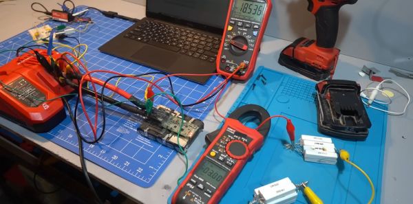
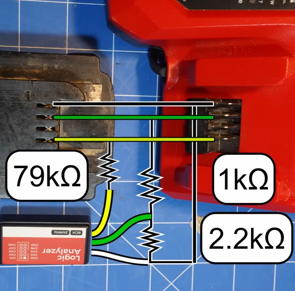
Putting these two things together, [Tool Scientist] was able to quickly get some of his M18 packs strapped down into the analysis chair for both passive analysis, as well as the effect of overvoltage, undervoltage, overheating and freezing the battery pack on the output reported by the battery’s BMS.
![One of the lists of commands and response messages obtained by [Tool Scientist] on YouTube.](https://hackaday.com/wp-content/uploads/2023/09/reverse_engineering_milwaukee_m18_redlink_protocol_startup_messages.jpg)
Hopefully the same inertia that prevents people from moving outside the designated power tool ecosystem due to the incompatible battery packs will also ensure that this level of knowledge will remain relevant for the foreseeable future, especially since the manufacturers of knock-off battery packs seem rather unwilling to share the results of their own reverse-engineering efforts.
Continue reading “Reverse-engineering The Milwaukee M18 Redlink Protocol”