Noctua wants to make life easier for fans of its…fans. To that end, the company has released a bevy of 3D models across its various product lines, all available to download for free.
If you’re not familiar with the company, Noctua specializes in high-quality cooling systems for the PC market. Its hope is that by freely providing 3D models of its components, it will aid aftermarket companies and DIYers that wish to integrate Noctua fans into their gear. In the company’s own words, these files are made available for “mechanical design, rendering, or animations.” They will let people check things like mountings and fitment without having to have the parts on hand, or to create demo visuals featuring the company’s products.
Don’t get too excited, though, because Noctua has already thought ahead. The company has specifically noted these parts aren’t intended for 3D printing, and critical components like fan blades have modified geometry so as to not compromise the companies IP. You could try and print these models, but they won’t perform like the real thing, and Noctua notes they shouldn’t be used for simulation purposes either. They’re intentionally not accurate to what the company actually sells in that regard.
That isn’t to say Noctua is totally against 3D printing. They have lots of parts available on Printables that they’d love you to try—everything from fan grilles to ducts to anti-vibration pads. Most are useful accessories—the kind of little bits of plastic that make using the products easier—that don’t threaten Noctua’s core product line in the marketplace.
If you’re whipping up a custom PC case and you want to kit it out with Noctua goodies, these models might help you refine your design. It’s funny how it’s such an opposite tactic to that taken by Honda, in terms of embracing the free exchange of 3D models on the open Internet. It’s a move that will surely be appreciated as a great convenience, and we’d love to see more companies follow this fine example.
Thanks to [irox] for the tip!


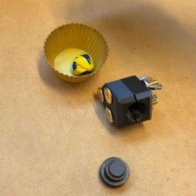 After previously trying out low-tech compression molding with a toaster oven and 3D printed molds, [future things] is back with a video that
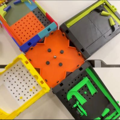 It seems fair to say that pinball machines are among the most universally loved gaming systems known today, yet the full-sized ones are both very expensive and very large, while even the good quality table-sized ones tend to be on the expensive side. That raises the question of whether a fully 3D printed pinball machine could at all be fun and not just feel like a cheapo toy? A recent video by [Steven] from [3D Printer Academy] on YouTube


