For eons, hacker minded people have looked at various items their pile of stuff, came up with an outlandish idea and thought “I wonder if it would work?” Some of us stop there, convincing ourselves that it’s a bad idea that could never work. Others of us such as [Peter Sripol] are well known for not just having those thoughts, but for having the grit to explore them to their impractical limit, such as is shown in the video below the break.
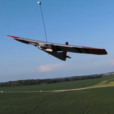
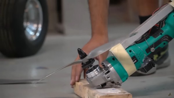
Peter begins by adapting a model airplane propeller to his 9500 RPM battery powered grinder, and then checks thrust with different propellers to see which seemed most efficient. Then [Peter] did what any aerospace engineer out of their right mind would do: He had his brother design the resulting aircraft, which was inspired by an obscure German WWII asymmetric aircraft design.
Did it fly? It did, and you can see a couple of iterations of it tooling around in the video. But what happened next was equally interesting: First, a grinder powered single bladed helicopter and its subsequent hilarious failure, and its slightly more successful successor.
We’ve of course covered many angle grinder hacks, such as this fixture for perfect cuts (something notoriously difficult to do with a handheld grinder), but this is the first time we’ve seen an angle grinder fly out of more than frustration. Do you have your own angle grinder hack to spin our way? Be sure to let the Tip Line know!
Continue reading “Power Tool Hack Takes A New Angle On RC Power Plants”