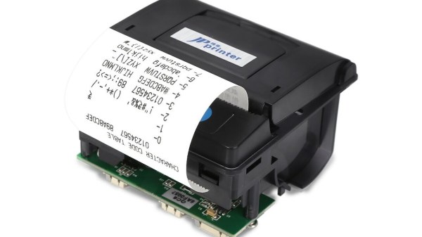
[Ziggurat29] had been playing around with infrared protocols, and realized he had a spare point-of-sale printer kicking around in his junk box. So he decided to whip up his own calculator infrared printer by bolting on an STM32 Blue Pill module and an IR receiver. [Ziggurat29] initially thought such a homemade printer would be cheaper than a commercial HP 82240 IR printer, even a used one. In hindsight, these point-of-sale printers can be pricey. If you don’t have one laying around, it may be cheaper to buy one, but not as fun as building it yourself.
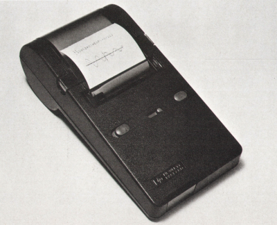
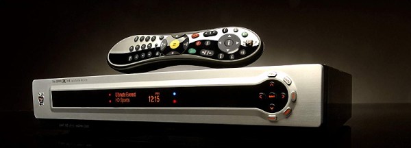
It used to be commonplace for calculators to have a printing mechanism — even entirely mechanical adding machines often had them. As electronic calculators became the norm, the printer began to fade away. Back in 1987, HP introduced a portable calculator printer, the HP 82240A (see HP Journal Oct 1987). The calculator could print using a one-way infrared protocol which came to be known as Redeye. This made good sense, since not every one needs a printing calculator. As well, if you had one of these printers, it could be used with multiple calculators. Later in 1991, HP added a bi-directional infrared link called SIR beginning with the HP 48SX calculator (see HP Journal Jun 1991), allowing calculators to communicate with each other or with an IR-equipped PC. Finally HP and other companies teamed up in 1995 to create the IrDA standards you are probably more familiar with. But a bunch of Redeye and SIR devices are still floating around, and even some modern calculators like SwissMicros offerings can still output to these printers.
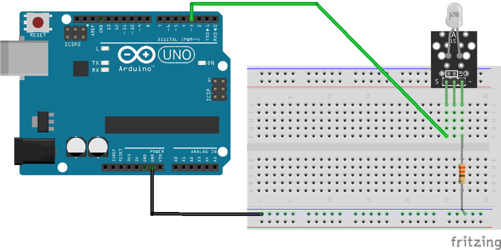
If you want to make your own IR printer, be sure to check out [ziggurat29]’s Hackaday.io project. Also [Martin Hepperle] has an excellent writeup on an Arduino-based project on his site. We also covered a reverse project way back in 2011, an adaptor that prints over IR from wired serial signals. Have you found a printing calculator, or a standalone printer like this, to be useful in your workflow? Let us know in the comments below.