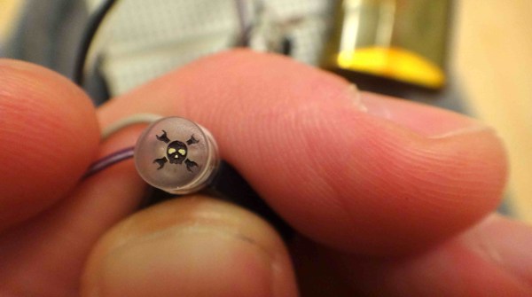
Here’s another Trinket Contest entry that was interesting enough for its own feature. [Adam] made his own Hackaday version of the Bat signal. It’s not nearly as big, but the concept is the same. Using this single modified LED he’s able to project a 12″ image that seems quite well-defined (more pictures below).
The LED is one he pulled from an old flashlight. After sanding the dome flat he made a jig which positioned it inside of his laser cutter. From there he etched the 0.1″ logo and filled the negative space with some ink. The remaining surface was polished to help the light shine through, then positioned in front of a jeweler’s loupe to magnify the image.
There’s just a couple of hours left before the Trinket Contest draws to a close. Get your entry in for a chance to win!
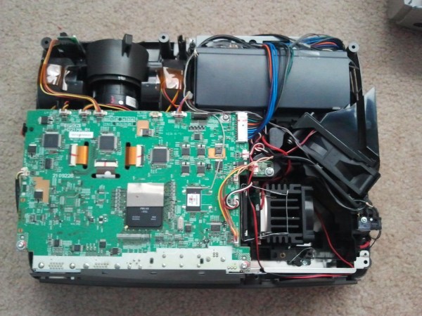
Projector bulbs can be incredibly expensive to replace. Sometimes it’s more cost efficient to just buy a whole new projector instead of a new bulb. [Shawn] recently found a nice deal on an ‘as is’ Epson EMP-S4 on eBay and decided to take a chance. He assumed it probably worked with the exception of the missing lamp the seller mentioned. His suspicions were correct, and one custom LED mod later, his projector was up and rolling.
Without a stock lamp installed, the projector would give an error message and shut itself off. So, the first step was to wire up a little bypass. Once that was taken care of, [Shawn] installed a 30W 2000 lumen LED and custom fit an old Pentium CPU heatsink to keep the LEDs temperature down. He also wired up the heatsink fan in parallel with the stock exhaust fan for good measure. Optical lenses help focus the light, and some custom wiring makes the LED turn on and off just like the stock lamp would.
In the end, his first experiment was a success, but [Shawn] wants to try an 8000 lumen 100W LED to make it about as bright as the stock lamp was. Check out a little video walkthrough after the break.
There’s a certain mystique about old home movies and 8mm film; whether it’s footage from a family gathering from 40 years ago or a stop-motion animation you made when you were 12, there’s an immediacy for film that the VHS tapes from your family’s first camcorder can’t match. [Teslas Moustache] has been getting into 8mm cameras and projectors, so when he came across a 8mm/super 8 projector that needed a bulb, he knew he had a worthwhile project on his hands.
To replace the burnt-out and very expensive to replace incandescent bulb, [Teslas] sourced a very bright star LED from Jameco. This 1 Watt LED puts out more than enough light to project a frame of film onto a screen and fortunately doesn’t get as hot as the stock bulb.
To power the LED, [Teslas] used a cell phone charger powered from the 120 VAC incandescent socket to supply the requisite 5 Volts at 1 Amp (Ohm’s Law works on coffee) power for the LED. Right now, there’s still the matter of fabricating a nice enclosure to mount the LED and charger in the bulb socket, but once [Teslas] figures that out, he’ll have a very nice 8mm projector on his hands.
[Devon] recently repaired a handful of Phillips LCD projectors which he was quite excited to use. The only problem is that he didn’t want to mess with replacing the bulbs after every 2000 hours of use at $100 apiece. He was pretty confident that he could find a better way to drive the projectors, so he disassembled them once more and started looking around for bulb replacements.
He figured that a high-powered LED would do the trick, so he ordered a handful of parts and went about his first retrofit. Using his oscilloscope, he found that the control board pulses the high voltage board when the projector is powered on, and continues to pulse a signal until the machine is turned off. At this point, the HV board powers down the bulb.
He created a small circuit using a PIC that is used to interpret the initial pulse from the control board as well as watch for the steady “heartbeat” pulses that occur while the projector is powered on. This board is used to control the driver board for the high-powered LED he purchased.
His bulb replacement works well as far as color fidelity is concerned, but is not nearly as bright as he hoped for. He has plans to source some far brighter LEDs or automobile HID lighting in the very near future, and we look forward to seeing if he can match the brightness of the original bulbs.
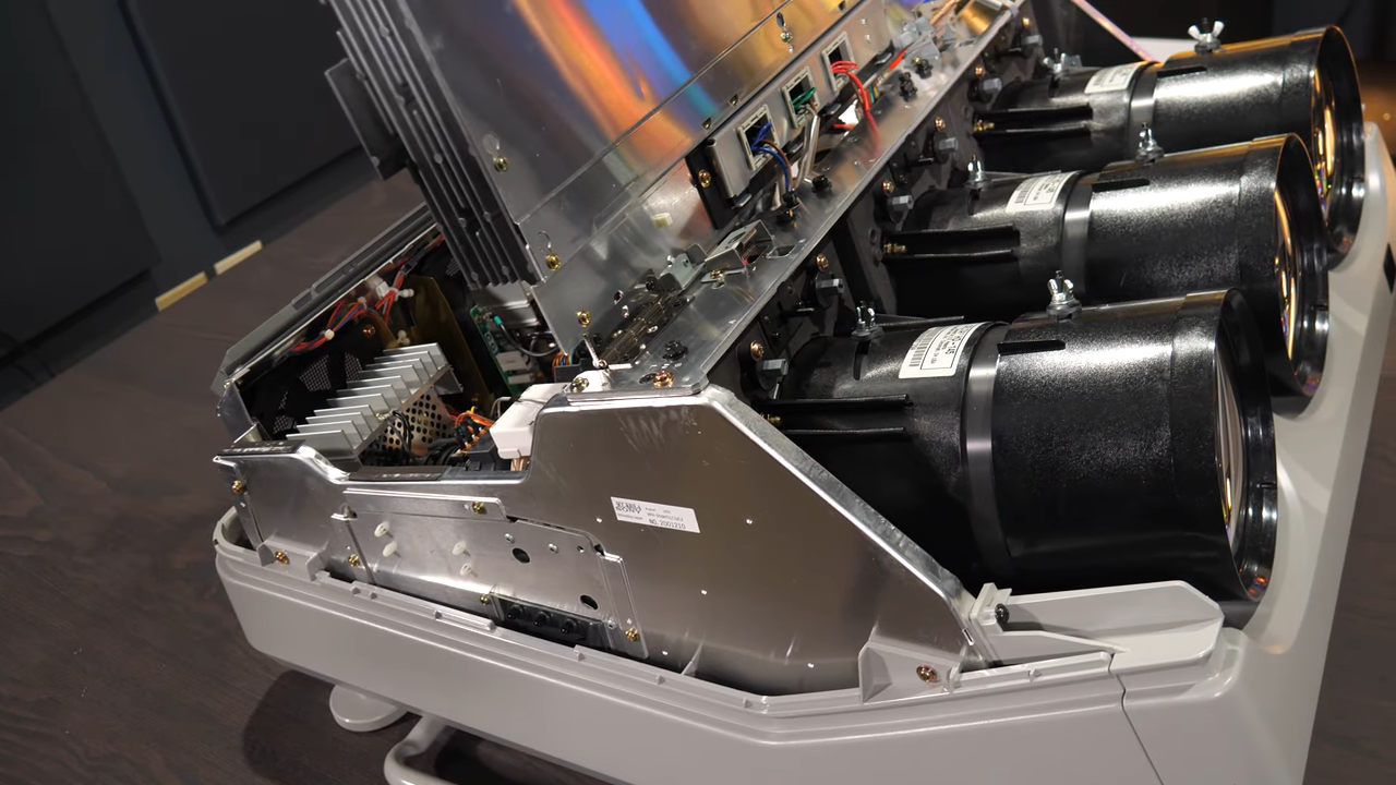
CRT monitors: there’s nothing quite like ’em. But did you know that video projectors used to use CRTs? A trio of monochrome CRTs, in fact: one for each color; red, green, and blue. By their powers combined, these monsters were capable of fantastic resolution and image quality. Despite being nowhere near as bright as modern projectors, after being properly set up, [Technology Connections] says it’s still one of the best projected images he has seen outside of a movie theatre.
After a twenty-minute startup to reach thermal equilibrium, one can settle down with a chunky service manual for a ponderous calibration process involving an enormous remote control. The reward is a fantastic (albeit brightness-limited) picture.
Still, these projectors had drawbacks. They were limited in brightness, of course. But they were also complex, labor-intensive beasts to set up and calibrate. On the other hand, at least they were heavy.
[Technology Connections] gives us a good look at the Sony VPH-D50HT Mark II CRT Projector in its tri-lobed, liquid-cooled glory. This model is a relic by today’s standards, but natively supports 1080i via component video input and even preserves image quality and resolution by reshaping the image in each CRT to perform things like keystone correction, thus compensating for projection angle right at the source. Being an analog device, there is no hint of screen door effect or any other digital artifact. The picture is just there, limited only by the specks of phosphor on the face of each tube.
Converging and calibrating three separate projectors really was a nontrivial undertaking. There are some similarities to the big screen rear-projection TVs of the 90s and early 2000s (which were then displaced by plasma and flat-panel LCD displays). Unlike enclosed rear-projection TVs, the screen for projectors was not fixed, which meant all that calibration needed to be done on-site. A walkthrough of what that process was like — done with the help of many test patterns and a remote control that is as monstrous as it is confusing — starts at 15:35 in the video below.
Like rear-projection TVs, these projectors were displaced by newer technologies that were lighter, brighter, and easier to use. Still, just like other CRT displays, there was nothing quite like them. And if you find esoteric projector technologies intriguing, we have a feeling you will love the Eidophor.
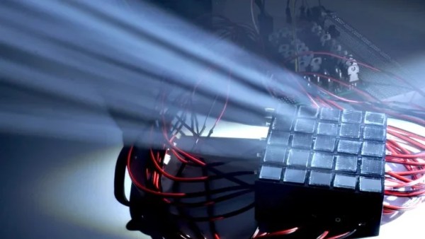
Texas Instruments developed digital mirror devices, and the subsequent digital light processing (DLP) projector, starting in the late 1980s. The technology is a wondrous and fanciful application of micro-scale electronics and optics. Most of us that have tangled with these devices have had to learn their mode of operation from diagrams and our own imagination. But what if you just built one at a large enough scale that you could see how it worked? Well, [jbumstead] did just that!
A real Digital Micromirror Device (DMD) consists of hundreds of thousands of mirrors, which would be impractical to recreate. This build settles for a simpler 5×5 array made using half-inch square mirrors. It uses solenoids to move each individual mirror between a flat and angled position to create the display. The solenoids are all under the command of an Arduino Mega which controls the overall state of the display and shows various patterns.
It’s not perfect, with the mirrors not quite matching in angles at all times, but it demonstrates the concept perfectly well. When you see it in action with light bouncing off it, you can easily understand how this could be used to make a display of many thousands of pixels in a projector arrangement. We’ve featured some other DLP hacks before, too, so dive in if you’re interested.
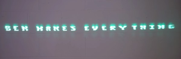
Spinning hard drives are being phased out of most consumer-grade computers in favor of faster technology like solid-state drives and their various interfaces. But there’s still millions of them in circulation that will eventually get pulled from service — so what do we do with them? If you’ve got one that would otherwise be going in the garbage, they can be turned into some other interesting devices like this laser text projector.
Even the slowest drives spin at around 5000 RPM, which is perfect for this type of application. The device works by mounting twelve mirrors, each at a slightly different angle, on a drum which is spun by the drive’s motor. Bouncing a laser off of the spinning drum results in a projection of twelve horizontal lines. By rapidly switching the laser on and off depending on which mirror it’s pointing at, the length of each line can be controlled.
Thanks to persistence of vision, that allows you to show text on the surface that the laser is projected on. At speeds this high, it took [Ben] of Ben Makes Everything quite a few iterations to get it to a usable space. From sensors that were too slow to lasers not bright enough to 3D prints that were not accurate enough, he goes through the design of his build and the process in excellent detail.
After solving all of the problems including building his own constant-current laser power supply, and burning up a few laser diodes in the process, [Ben] has a laser projector capable of displaying readable text at a great distance which is also portable, running on a 12 V power supply. There are some possible areas of improvement that he notes as well, such as an unbalanced 3D printed part causing a bit of a wobble and the Arduino controller not being fast enough for more text. But it’s an impressive project nonetheless, similar to a two-mirror version we saw some time ago but with the ability to display text as well.