Retrotechtacular: The $175,000 Laser Printer

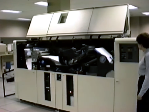
Laser printers today are cheap and readily available. But in 1976, they were the height of printing technology. The IBM 3800 was the $175,000 printer to have in that year. (Video, embedded below.) But you couldn’t have one on your desktop. Even if you could afford it, the thing is the size of a car, and we don’t even want to guess what it weighs. The printer took tractor-fed continuous form paper and could do 167 pages a minute at about 150 dots per inch (actually 180 x 144). For the record, that was as much as 1.7 miles of paper an hour!

In those days, people who would use this printer traditionally had massive banks of noisy impact printers. We imagine this device saved many data processing person’s hearing. Compared to a modern laser printer, though, it needed a lot of maintenance. For example, the initial models needed a xenon flash lamp replaced every month, although later models could go years on one bulb. Looking at some of the hardware in the video, it was probably made closer to the end of life for these printers which were made through 1999.

Continue reading “Retrotechtacular: The $175,000 Laser Printer”

Converting A Polaroid SX70 Camera To Use 600 Film

These days, it’s possible to buy a number of different Polaroid instant cameras new off the shelf. That’s largely thanks to the retro resurgence that has buoyed interest in everything from vinyl records to analog synthesizers. However, if you’re truly old-school, you might still be rocking a vintage Polaroid SX-70 camera. Thankfully, there’s a way to convert these old rigs to work properly with the more popular modern 600 film.

The interesting thing about the SX-70 camera design is that its shutter speed and aperture setting are essentially linked together as the aperture and shutter assembly are combined into one unit with a variable tear-drop shaped opening. Thus, the timing of the shutter opening and closing and the extent to which it opens are what determines exposure and aperture.

Thankfully, [Jake Bright] has learned a lot about these unique cameras and exactly how this complex system operates. He shares his tips on firstly restoring the camera to factory-grade operation, and then the methods in which they may be converted to work with modern film. Fundamentally, it’s about changing capacitors or resistors to change the shutter/aperture timing. However, do it blindly and you’ll have little success. You first need to understand the camera’s mechanics, pneumatics, and its “Electric Eye” control system before you can get things dialed in just so.

We’ve seldom seen such a great deep dive into a camera outside of full-fat engineering documentation. [Jake] should be commended on his deep understanding and command of these fine instant cameras from yesteryear. May the Polaroid picture never die. Video after the break. Continue reading “Converting A Polaroid SX70 Camera To Use 600 Film”

Noble Graphs: Displaying Data With Neon Like Its 1972

In the days before every piece of equipment was an internet-connected box with an OLED display, engineers had to be a bit more creative with how they chose to communicate information to the user. Indicator lights, analog meters, and even Nixie tubes are just a few of the many methods employed, and are still in use today. There are, however, some more obscure (and arguably way cooler) indicators that have been lost to time.

[Aart Schipper] unearthed one such device while rummaging around in his father’s shed: a pair of Burroughs Bar Graph Glow-Transfer Displays. These marvelous glowing rectangles each have two bars (think the left and right signals on an audio meter, which is incidentally what they were often used for), each with 201 neon segments. Why 201, you may ask? The first segment on each bar is always illuminated, acting as a “pilot light” of sorts. This leaves 200 controllable segments per channel. Each segment is used to “ignite” its neighboring segment, something the manufacturer refers to as the “Glow-Transfer Principle.” By clever use of a three-phase clock and some comparators, each bar is controlled by one analog signal, keeping the wire count reasonably low.

Don’t get us wrong, the warm, comforting glow of Nixie tubes will always have a special place in our hearts, but neon bar graphs are just hard to beat. The two do have a similar aesthetic though, so here’s hoping we see them used together in a project soon.

Thanks to [Jan] for the tip!

Restoration Of A Thinkpad 701C

This is like ASMR for Hackers: restoration specialist [Polymatt] has put together a video of his work restoring a 1995 IBM Thinkpad 701c, the famous butterfly keyboard laptop. It’s an incredible bit of restoration, with a complete teardown and rebuild, even including remaking the decals and rubber feet.

[Polymatt] runs Project Butterfly, an excellent site for those who love these iconic laptops, offering advice and spare parts for restoring them. In this video, he does a complete teardown, taking the restored laptop completely apart, cleaning it out, and replacing parts that are beyond salvaging, like the battery, and replacing them. Finally, he puts the whole thing back together again and watches it boot up. It’s a great video that we’ve put below the break and is well worth watching if you wonder about how much work this sort of thing involves: the entire process took him over two years.

We’ve covered some of his work in the past, including the surprisingly complicated business of analyzing and replacing the Ni-Cad battery that the original laptop used. Continue reading “Restoration Of A Thinkpad 701C”

Learning About Ferroresonant Transformers While Fixing A 1970s Power Supply

Ferroresonant (constant voltage) transformer diagram. Secondary side is kept in full saturation with the tank, keeping voltage constant. (Credit: Usagi Electric)

While troubleshooting the power supply of a 1970s Centurion system, [Usagi Electrics] came across a fascinating feature of these units: the ferroresonant, or constant voltage transformer (CVT). The main difference between a regular transformer and a CVT is that the former has a quite direct correlation between the input and output voltage, as the magnetic flux induced on the primary side is directly translated to the secondary (output) side.

A CVT adds a second element on the secondary side in the form of a tank circuit (LC circuit) – essentially a large capacitor – along with a magnetic shunt that ‘short circuits’ part of the magnetic flux between the primary and secondary side. The result of this is that even as the primary side is kept well below the saturation point where efficiency plummets, the secondary side is kept within this saturation region, enabling a very constant output voltage across a wide range of input voltages. For the Centurion’s power supply this input range goes from 90 to 130 VAC.

Continue reading “Learning About Ferroresonant Transformers While Fixing A 1970s Power Supply”

Displays We Love Hacking: The HD44780 Family

There are too many different kinds of displays – some of them, you already know. I’d like to help you navigate the hobbyist-accessible display world – let’s take a journey together, technology by technology, get a high-level overview of everything you could want to know about it, and learn all the details you never knew you needed to know. In the end, I’d like you to be able to find the best displays for any project you might have in mind, whatever it could be.

There’s a HD44780 clone IC under this epoxy blob! CC0 1.0

Today, let’s take a look at a well-known LCD technology – the HD44780 displays, a type of display that we hobbyists have been working with since the 1980s. Its name comes from the HD44780 driver chip – a character display driver IC that connects to a raw display panel and provides an easy interface.

HD44780 displays are not known for power efficiency, cutting-edge technology, ultimate flexibility, or small size, for that matter. However, they’re tried and true, easy to drive, require little to no computing power on your MCU, and you will be able to buy them for the foreseeable future. They’re not about to get taken off the market, and they deserve a certain kind of place in our parts boxes, too.

If you work with HD44780 displays for a project or two, you might acquire a new useless superpower – noticing just how many HD44780 displays are still in use in all sorts of user-facing devices, public or private. Going out and about in your day-to-day life, you can encounter a familiar 16 x 2 grid of characters in cash registers, public transport ticket machines, home security panels, industrial and factory equipment, public coffee machines, and other microcontroller-assisted places of all kinds! Continue reading “Displays We Love Hacking: The HD44780 Family”

A purple PCB with a Raspberry Pi Pico and an MK3870 mask ROM microcontroller

A 1970s Mask ROM MCU Spills Its Secrets

If you buy any kind of electronic gadget today, chances are it’s powered by a microcontroller with a program stored in its internal flash ROM. That program’s code is often jealously guarded by the manufacturer, who will try their best to make sure you can’t just read back the chip’s contents by using lock bits or some sort of encryption. Things were more laid back in the 1970s and ’80s, when code was stored unencrypted in standard EPROM chips, or, for high-volume applications, in mask ROMs integrated in microcontrollers. Reading back the code of such micros was still very difficult because chips simply didn’t have a way of dumping their contents. [Andrew Menadue] ran into this issue when trying to repair an old HP calculator printer, and had to apply a clever hack to dump the contents of its Mostek MK3870 chip.

The main trick [Andrew] used was one discovered by [Sean Riddle] and explained on his website. It makes use of the fact that the MK3870 has a TEST pin that can be used to disable the mask ROM and load alternative program code directly into the micro’s processing core. By setting up a LOAD instruction pointing at a ROM location and briefly disabling test mode while that instruction is executed, the ROM’s contents can be read out by the externally loaded program.

Simple as this hack may seem, actually implementing it was tricky enough because of the strict timing requirements between signals on the clock pins, the data bus, and the TEST pin. [Andrew] got it to work on his Raspberry Pi Pico setup most of the time, but somehow the micro still returned a plainly wrong value every few hundred bytes. Not willing to spend too much time debugging this issue, [Andrew] applied a rather crude hack to his code: instead of reading each byte once, it runs the read cycle 200 times, and only returns a result when all 200 runs return the same value. Dumping the entire 4 kB of ROM now takes several minutes, but this isn’t much of an issue since [Andrew] only has one chip to read out.

If you do have a bucketload of MK3870 chips that you need to dump, you might want to try and optimize the code on [Andrew]’s GitHub page. It’s a lucky coincidence that the ‘3870 has the exploitable TEST feature; often, the only way to get inside mask ROM code is by decapping the chip and optically reading the bits one by one. Mask ROMs are great for very long term data storage, however.

Continue reading “A 1970s Mask ROM MCU Spills Its Secrets”