The Most Minimal WS2812B Driver

Whether you call them individually controllable RGB LEDs, WS2812, or NeoPixels, there’s no denying they are extremely popular and a staple of every glowey and blinkey project. Fresh off the reel, they’re nearly useless – you need a controller, and that has led to many people coming up with many different solutions to the same problem. Here’s another solution, notable because it’s the most minimal WS2812 driver we’ve ever seen.

The critical component in this build is NXP’s LPC810, an ARM Cortex M0+ in an 8-pin DIP package. Yes, it’s the only ARM in a DIP-8, but still able to run at 30MHz, and hold a 4kB program.

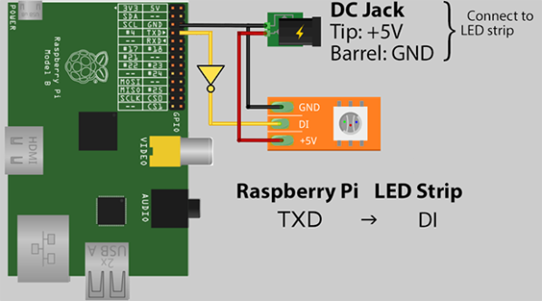
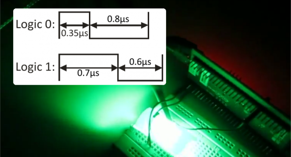
JeeLabs is using the SPI bus on the LPC810 to clock out data at the rate required by the LEDs. The only hardware required is a small LED to drop the voltage from 5V to 3.3V and a decoupling capacitor. Yes, you could easily get away with this as a one-component build.

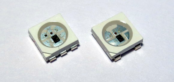
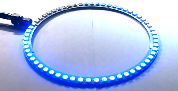
The build consists of a ring of sixty WS2812b RGB LEDs, and the chip dutifully clocking out bits at the correct rate. It’s the perfect start to an LED clock project, an Iron Man arc reactor (are we still doing those?), or just random blinkey LEDs stuffed into a wearable.

Thanks [Martyn] for sending this one in.

Measuring The Length Of WS2812 Strips

[Tim] discovered a simple way to measure the length of WS2812 addressable LED strips from a microcontroller. This is great for any project that can have an arbitrary length of addressable LED strip attached to it.

The simplest (and perhaps most reliable) way to measure strip length is by feeding the serial output pin of the end of the strip back to the microcontroller. The microcontroller keeps clocking bits into the strip until it receives data from the end of the strip. [Tim] didn’t want to run an additional signal to the end of his strip, so he found another solution.

[Tim] used the ADC of his microcontroller (an ATtiny) to measure supply voltage droop as LEDs are turned on. Each LED draws around 60mA at full brightness, so [Tim] sequentially turned on each LED and watched the ADC for slight voltage changes. If the voltage changed, there must be an LED at that address. [Tim] does note that this method is extremely dependent on the power supply used and only works on short strips. Check out his blog post for more details.

WS2812 at 670 kHz

Driving WS2812B Pixels, With DMA Based SPI

Typically bit-banging an I/O line is the common method of driving the WS2812B (WS2811) RGB LEDs. However, this ties up precious microcontroller cycles while it waits around to flip a bit. A less processor intensive method is to use one of the built-in Serial Peripheral Interface (SPI) modules. This is done using specially crafted data and baud rate settings, that when shifted out over the Serial Data Out (SDO) pin, recreate the needed WS2812B signal timing. Even when running in SPI mode, your hardware TX buffer size will limit how many pixels you can update without CPU intervention.

[Henrik] gets around this limitation by using peripheral DMA (Direct Memory Access) to the SPI module in the Microchip PIC32MX250F128B microcontroller. Once properly configured, the DMA controller will auto increment through the defined section of DMA RAM, sending the pixel data over to the SPI module. Since the DMA controller takes care of the transfer, the micro is free to do other things. This makes all of DMA memory your display buffer. And leaves plenty of precious microcontroller cycles available to calculate what patterns you want the RGB LEDs to display.

Source code is available at the above link for those who would like to peruse, or try it out. This is part of [Henrik’s] Pixel Art Project. Video of DMA based SPI pixels after the break:

Continue reading “Driving WS2812B Pixels, With DMA Based SPI”

WS2812b Ambilight Clone For The Raspi

For how often the Raspberry Pi is used as a media server, and how easy it is to connect a bunch of LEDs to the GPIO pins on the Pi, we’re surprised we haven’t seen something like Hyperion before. It uses the extremely common WS2812b individually controllable RGB LEDs to surround the wall behind your TV with the colors on the edges of the screen.

One of the big features of Hyperion is the huge number of LEDs it’s able to control; a 50 LED strip only eats up about 1.5% of the Pi’s CPU. It does this with a “Mini UART” implemented on the Pi running at 2MHz.

There’s only one additional component needed to run a gigantic strip of RGB LEDs with a Pi – an inverter of some sort made with an HCT-series logic chip. After that, you’ll only need to connect the power and enjoy a blinding display behind your TV or monitor.

Thanks [emuboy] for sending this one in.


Breadboardable WS2812 LEDs

LED

Hackaday sees a ton of projects featuring the WS2812 series of digitally controllable RGB LEDs, in the form of bare chips, RGB LED strips, or some form of Adafruit’s NeoPixels. All these WS2812 LED products have one thing in common – they’re chip LEDs, making some projects difficult to realize. Now there’s a new member of the WS2812 family – a through-hole LED version – that should be available through the usual sources sometime later this year.

The key difference between these and the usual WS2812 LEDs is the packaging; these are 8mm LEDs with pins for power, ground, data in, and data out. With the preexisting libraries, this 8mm LED should work just the same as any other WS2812 LED.

Aside from a through-hole package, these new LEDs are very diffuse and aren’t as blinding as the normal chip LEDs. If you want to pick up a few of these LEDs, they’re available here, 13 LEDs for $15. There’s a lot of potential here for RGB LED cubes, something we hope to see sooner rather than later.

Rewriting WS2812 Driver Libraries For Optimization

ws2812_compared

We like [Tim’s] drive for improvement. He wrote a WS2812 driver library that works with AVR and ARM Cortex-M0 microcontrollers, but he wasn’t satisfied with how much of the controller’s resources the library used to simply output the required timing signal for these LED modules. When he set out to build version 2.0, he dug much deeper than just optimizing his own code.

We remember [Tim] from his project reverse engineering a candle flicker LED. This time, he’s done more reverse engineering by comparing the actual timing performance of the WS2812(B) module with its published specs. He learned that although several timing aspects require precision, others can be fudged a little bit. To figure out which ones, [Tim] used an ATtiny85 as a signal-generator and monitored performance results with a Saleae logic analyzer. Of course, to even talk about these advances you need to know something about the timing scheme, so [Tim] provides a quick run-through of the protocol as part of his write-up.

Click the top link to read his findings and how he used them to write the new library, which is stored in his GitHub repository.

Using DMA To Drive WS2812 LED Pixels

It’s pretty well known by now that the LED pixel hardware which is starting to be commonplace, both WS2811 and WS2812, needs pretty strict timing in order to address them. There are libraries out there which mean almost no work on your part, but that’s no fun. [Elia] started looking into what it takes to drive the hardware, trying out a few 8-bit micros before moving to 32-bit with the help of an STM32VL Discovery Board. The move to a beefier processor brings a lot of speed, but why bit bang everything? He came up with a way to use the PWM and DMA features of the chip to drive the LEDs.

DMA is the Direct Memory Access unit that allows you to change the values being sent to the pixel without interrupting the processor. This is done by pre-loading the data at a memory location. This buffer is automatically read by the DMA unit — its values are used to set the PWM timer compare trigger in order to send out logic values show in the diagram above.

If you do want to delve further into this topic here’s a collection of techniques for driving the WS2811.

Continue reading “Using DMA To Drive WS2812 LED Pixels”