Ribbon Cable Repair Saves Touch ID

Some might consider a broken ribbon cable to be unsalvagable. They’re delicate and fragile as can be, and sometimes just fussing with them further is enough to cause additional damage. However, with the right set of skills, it’s sometimes possible to achieve the unthinkable. As [Master Liu] demonstrates, you can indeed repair a broken ribbon cable, even a tiny one.

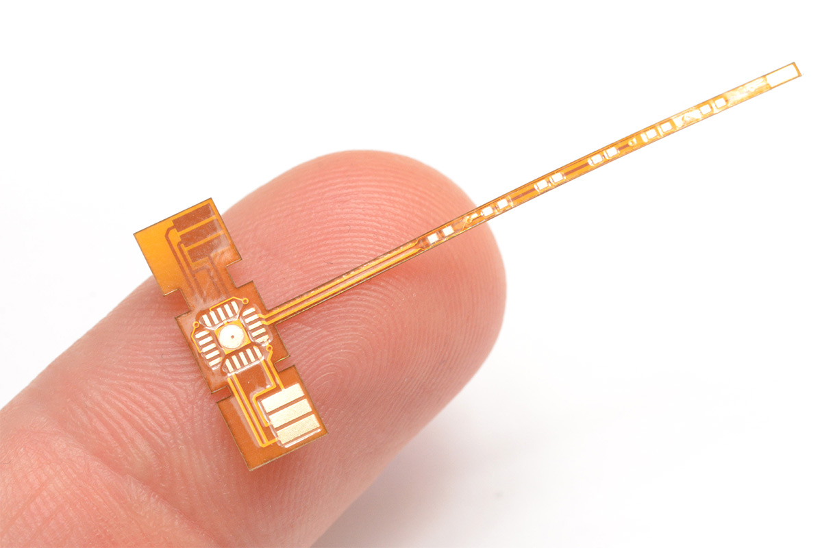
The video concerns a ribbon cable linked to a Touch ID fingerprint sensor from an Apple device. It’s common to break these ribbon cables when repairing a phone, and doing so causes major problems. The Touch ID device is paired with the host phone, and cannot easily be replaced. Thus, repair is justified if at all possible.

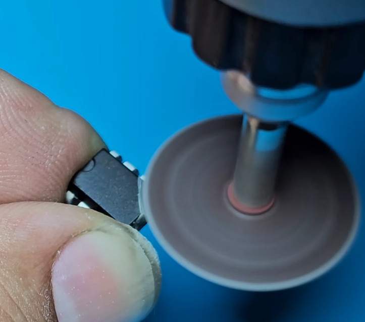
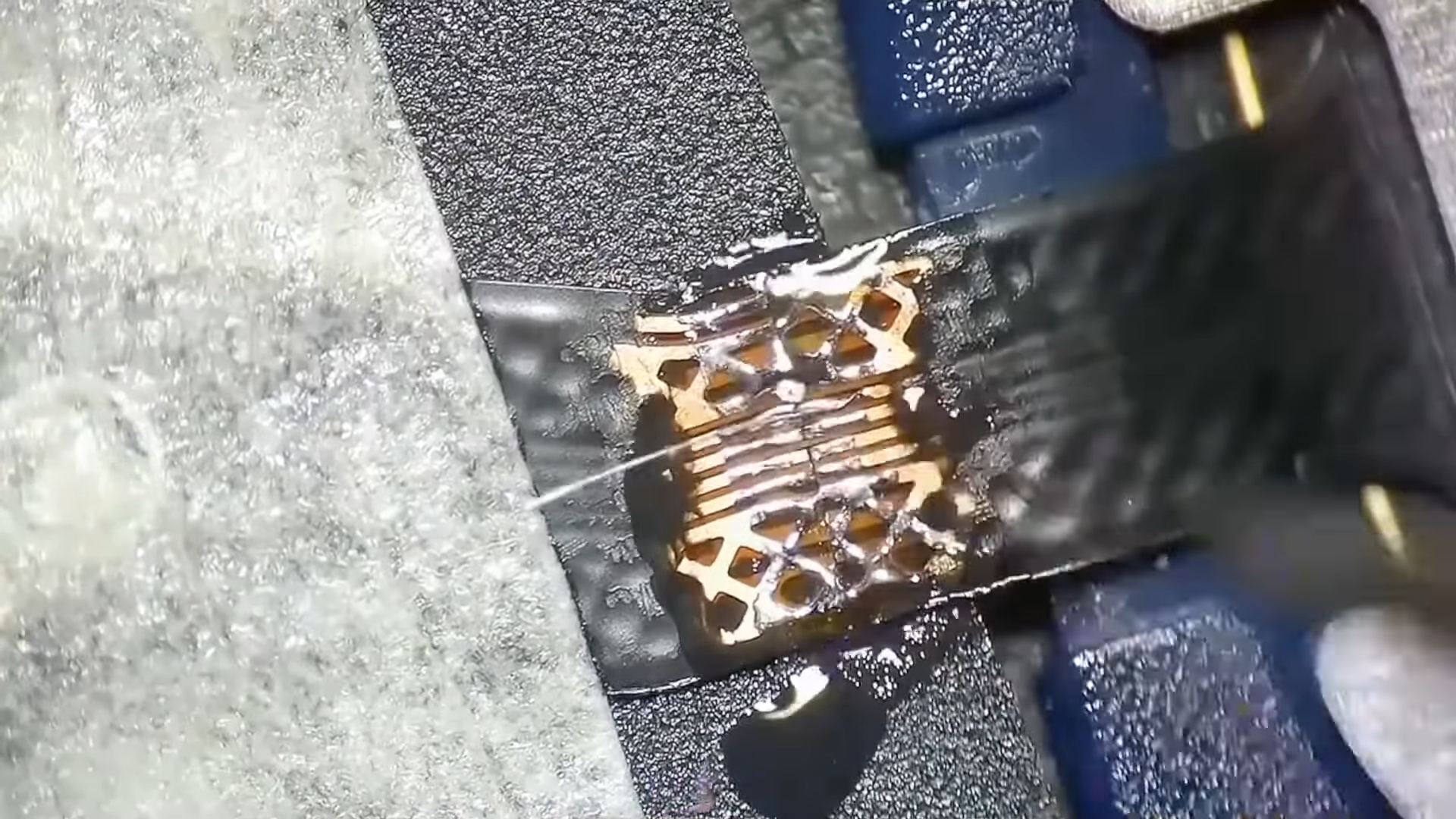
The repair involves scraping back the outer coating on the two sections of ribbon cable to reveal the copper pads underneath. The copper is then coated with flux and solder to prepare them to be rejoined. Ultra-fine strands of wire are used to join the individual traces. Then, the repaired section is coated in some kind of sealant or epoxy to hold the joint together and protect it from failing again. The theory is easy, it’s just the execution that’s hard.

Ribbon cable repair is becoming one of our favorite topics of late. Sometimes you just need a steady hand and the guts to have a go. Video after the break.

Continue reading “Ribbon Cable Repair Saves Touch ID”

Screenshot of the YouTube channel videos list, showing a number of videos like the ones described in this article.

[DiyOtaku] Gives Old Devices A New Life

Sometimes we get sent a tip that isn’t just a single article or video, but an entire blog or YouTube channel. Today’s channel, [Diy Otaku], is absolutely worth a watch if you want someone see giving a second life to legendary handheld devices, and our creator has been going at it for a while. A common theme in most of the videos so far – taking an old phone or a weathered gaming console, and improving upon them in a meaningful way, whether it’s lovingly restoring them, turning them into a gaming console for your off days, upgrading the battery, or repairing a common fault.

The hacks here are as detailed as they are respectful to the technology they work on. The recent video about putting a laptop touchpad into a game controller, for instance, has the creator caringly replace the controller’s epoxy blob heart with a Pro Micro while preserving the original board for all its graphite-covered pads. The touchpad is the same used in an earlier video to restore a GPD Micro PC with a broken touchpad, a device that you can see our hacker use in a later video running FreeCAD, helping them design a 18650 battery shell for a PSP about to receive a 6000 mAh battery upgrade.

Continue reading “[DiyOtaku] Gives Old Devices A New Life”

Emergency DIP Pin Repair For Anyone

Who has not at some point in their lives experienced the horror of a pin on a DIP package breaking off? It’s generally game over, but what if you don’t have another chip handy to substitute? It’s time to carefully grind away some of the epoxy and solder on a new pin, as [Zafer Yildiz] has done in the video below the break.

The technique relies on the pins continuing horizontally inside the package , such that they provide a flat surface. He’s grinding with the disk on a rotary tool, we have to say we’d use one of the more delicate grinding heads for something more akin to a miniature die grinder.

Once the flat metal surface is exposed, the chip is placed in a socket, and a new pin is cut from the leg of a TO-220 power device. This is carefully bent over, inserted in the socket, and soldered into place. The whole socket and chip arrangement is then used in place of the chip, making for something a little bulky but one infinitely preferable to having to junk the device.

There are many useful skills to be learned when it comes to reworking, and we’ve covered a few in our time. Most recently we saw a guide to lifting SMD pins.

Continue reading “Emergency DIP Pin Repair For Anyone”

Spice Up Your Earrings With Microelectronics

We’ve covered [mitxela] in the past and if you know him, you’ll likely know him for putting the micro in microelectronics. This year, he’s at it again with his LED Industrial Piercing.

A T-shaped flexible PCB that is smaller than an index finger
This tiny PCB is really pushing the limits of fabrication

Inspired by the absolutely tiny 0402 LEDs and industrial piercings, [mitxela] started thinking of a way to construct the 5cm long device. He found some normal LED earrings to steal the battery compartment from. Then, with a tick needle and some more steel, he created a new industrial earring with some holes.

Of course, no [mitxela] project is complete without comically tiny microsoldering and this project makes the VQFN ATTiny he used look large. He puts his PCB suppliers to the test with a merely 1mm wide flex PCB for the LEDs to be mounted on. Finally, he combines the flex PCB, the earring and some epoxy to create yet another piece of LED jewelry.

Video after the break.
Continue reading “Spice Up Your Earrings With Microelectronics”

You Can’t Make What You Can’t Measure

What’s the most-used tool on your bench? For me, it’s probably a multimeter, although that’s maybe a tie with my oscilloscope. Maybe after that, the soldering iron and wire strippers, or my favorite forceps. Calipers must rate in there somewhere too, but maybe a little further down. Still, the top place, and half of my desert-island top-10, go to measuring gear.

That’s because any debugging, investigation, or experimentation always starts with getting some visibility on the problem. And the less visible the physical quantity, the more necessary to tool. For circuits, that means figuring out where all the voltages lie, and you obviously can’t just guess there. A couple months ago, I was doing some epoxy and fiberglass work, and needed to draw a 1/2 atmosphere vacuum. That’s not the kind of quantity you can just eyeball. You need the right measurement tool.

A few weeks ago, I wrote about my disappointment in receiving a fan that wouldn’t push my coffee beans around in the homemade roaster. How could I have avoided this debacle? By figuring out the pressure differential needed and buying a fan that’s appropriately rated. But I lacked pressure and flow meters.

Now that I think about it, I could have scavenged the pressure meter from the fiberglassing rig, and given that a go, but with the cheap cost of sensors and amplifiers, I’ll probably just purpose-build something. I’m still not sure how I’ll measure the flow; maybe I’ll just cheese out and buy a cheap wind-speed meter.

When people think of tools, they mostly think of the “doers”: the wrenches and the hammers of this world. But today, let’s all raise a calibrated 350 ml glass to the “measurers”. Without you, we’d be wandering around in the dark.

Putting The Magic Smoke Back Into A Dodgy Spectrum Analyzer

The trouble with fixing electronics is that most devices are just black boxes — literally. Tear it down, look inside, but it usually doesn’t matter — all you see are black epoxy blobs, taunting you with the fact that one or more of them are dead with no external indication of the culprit.

Sometimes, though, you get lucky, as [FeedbackLoop] did with this Rigol spectrum analyzer fix. The instrument powered up and sort of worked, but the noise floor was unacceptably high. Even before opening it up, there was clearly a problem; in general, spectrum analyzers shouldn’t rattle. Upon teardown, it was clear that someone had been inside before and got reassembly wrong, with a loose fastener and some obviously shorted components to show for it. But while the scorched remains of components made a great place to start diagnosis, it doesn’t mean the fix was going to be easy.

Figuring out the values of the nuked components required a little detective work. The blast zone seemed to once hold a couple of resistors, a capacitor, a set of PIN diodes, and a couple of tiny inductors. Also nearby were a pair of chips, sadly with the markings lasered off. With some online snooping and a little bit of common sense, [FeedbackLoop] was able to come up with plausible values for most of these — even the chips, which turned out to be HMC221 RF switches.

Cleaning up the board was a bit of a chore — the shorted components left quite a crater in the board, which was filled with CA glue, and a bunch of missing pads. This called for some SMD soldering heroics, which sadly didn’t fix the noise problem. Replacing the two RF switches and the PIN diodes seemed to fix the problem, albeit at the cost of some loss. Sometimes, good enough is good enough.

This isn’t the first time [FeedbackLoop] has gotten lucky with choice test equipment in need of repairs — this memory module transplant on a scopemeter comes to mind.

Continue reading “Putting The Magic Smoke Back Into A Dodgy Spectrum Analyzer”

Retro Gadgets: The 1974 Breadboard Project

It is hard to imagine experimenting with electronics without the ubiquitous solderless breadboard. We are sure you have a few within arm’s reach. The little plastic wonders make it easy to throw together a circuit, try it, and then tear it down again. But, surprisingly, breadboards of that type haven’t always been around, and — for a while — they were also an expensive item. Maybe that’s what motivated [R. G. Cooper] to build Slip-n-Clip — his system for quickly building circuits that he published in a 1974 edition of the magazine Elementary Electronics.

The system isn’t really what you would think of as a breadboard today, but it was effective and certainly cheap to build. The biggest problem? It wasn’t something you’d use with DIP ICs. But in the early 1970s, you might not be building very much with ICs, and the ones you used might be in oddball transistor-like packages. Things were strange in the 70s!

A Brief History of Breadboards

In the very old days, people built radios and such on wooden substrates that were actually bread-cutting boards. That’s where the name came from. It was common to draw a diagram with the physical layout you had in mind, glue it to the board, and use it as a guide for building and troubleshooting. Wood was easy to drill and cut. A nail or a thumbtack would make dandy terminals. Probably the last time we saw that done was about a dozen years ago in Make Magazine. Even then, it was only a novelty — few people still build circuits like this, but you can see how [Colin] did it in the video below.

Continue reading “Retro Gadgets: The 1974 Breadboard Project”