CO2 Laser Decapping To Fix Soldering Mistake

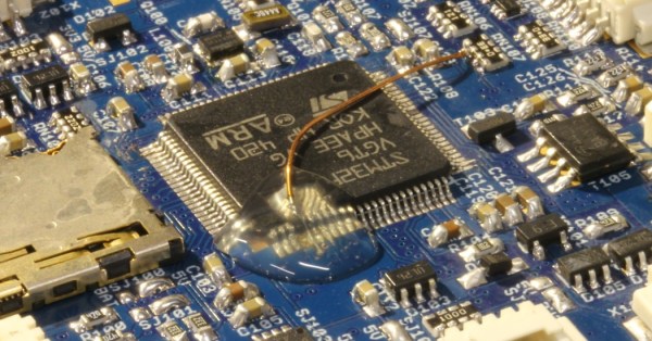
[Carsten] messed up. He was soldering an ARM CPU onto a quadcopter board in haste, failed to notice that the soldering iron was turned up to eleven, and pulled some of the traces up off the PCB. In the process of trying to fix that, he broke three pins off of the 100-pin CPU. The situation was going from bad to worse.

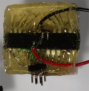
Instead of admitting defeat, or maybe reflowing the CPU off of the board, [Carsten] lasered the epoxy case off of the chip down to the lead frame and worked a little magic with some magnet wire. A sweet piece of work, to be sure!

Continue reading “CO2 Laser Decapping To Fix Soldering Mistake”

Metal Inlays Using A Bit Of Solder

metal inlay

Looking for a unique way to add a nice metal inlay to finish off your project? [Ben Krasnow] shows us how using a CNC router, a bit of solder, and a lot of sand paper!

It’s actually a pretty simple job — Of course, that’s only if you have a CNC machine. [Ben] started by engraving his inlay using his handy CNC mill, and then sanding off any rough spots. He then filled the engraving with acid flux paste, got out his MAPP gas torch and started dripping solder into the piece. Once everything was covered, he started sanding it, from 60 grit all the way to 600 grit for a nice polished finish. The results speak for themselves.

An easier method of this could also be achieved using plastic and epoxy, instead of brass and solder. One of the biggest problems with the solder is bubbling, which can cause voids which will appear when you are sanding — so you might have to do a second pass with the solder.

[Ben Krasnow] is an interesting character. He’s sought out the perfect cookie, made his own CT scanner at home, explained the various heat treatments of steel — and even installed LEDs into his contact lenses just for kicks!

[Thanks Fabien!]

Hand Soldering BGA Wafer Chips

And here we’ve been complaining about Flat Pack No-Lead chips when this guy is prototyping with Ball Grid Array in a Wafer-Level Chip Scale Package (WLCSP). Haven’t heard that acronym before? Neither had we. It means you get the silicon wafer without a plastic housing in order to save space in your design. Want to use that on a breadboard. You’re crazy!

Eh, that’s just a knee jerk reaction. The wafer-level isn’t that unorthodox as far as manufacturing goes. It’s something like chip on board electronics which have that black blob of epoxy sealing them after the connections are made. This image shows those connections which use magnet wire on a DIP breakout board. [Jason] used epoxy to glue the wafer down before grabbing his iron. It took 90 minutes to solder the nine connections, but his second attempt cut that process down to just 20. After a round of testing he used more epoxy to completely encase the chip and wires.

It works for parts with low pin-counts. But add one row/column and you’re talking about making sixteen perfect connections instead of just nine.

8×8 LED Matrix Pendant Sealed In A Block Of Epoxy

8x8-led-pendant

This is the back side of [Dmitry Grinberg’s] 8×8 LED matrix pendant. He had seen the other projects that used a 5×7 grid but wasn’t really satisfied with the figures that can be drawn in that confined area when each pixel has only the option of being on or off. His offering increases the drawing area and includes the ability to display each pixel at several different levels.

He’s using an ATmega328 microcontroller soldered directly to the pins on the back of the LED module. He mapped out the IO in his firmware to make the soldering as easy as possible. To protect the hardware he fashioned a mold around the edges of the LED package using duct tape. The tape held epoxy in place as it hardened, encasing the microcontroller and holding the power wires and ICSP header tightly.

After the break you can see about six seconds of the device in action. The four levels of brightness for each pixel really do make quite a difference!

Continue reading “8×8 LED Matrix Pendant Sealed In A Block Of Epoxy”

Toaster Oven Forgoes Pop-Tarts, Reflows Solder

For SMD work, solder paste and a heat gun is great. Heat guns aren’t the cheapest thing, so [Karel] decided to make cheap reflow oven out of a toaster oven. With a PCB taken from a laminator temperature control board, the build was fairly successful, so [Karel] decided to add a thermistor to his oven.

There was a problem with placing this thermistor near the board: solder melts in a reflow oven, so [Karel] needed to figure how to connect the thermistor to the control board outside the oven. The solution was crimping thin copper tubing to the thermistor leads and passing that tube through the wall of the oven. Epoxy was used to avoid an electrical short. A low tech solution, but very effective. After applying some solder paste and going in the oven, this board looks very clean. There are a few solder bridges, but nothing a wick can’t take care of.

[Karel] is now working on an update to the temperature controller that controls the oven over a serial connection. Check out the video of a few temperature cycles after the break.

Continue reading “Toaster Oven Forgoes Pop-Tarts, Reflows Solder”

Tools: Aoyue 968 3-in-1 Soldering And Rework Station

The $10 “fire-starter” is the most common beginner soldering iron. These are simple irons with a hot end, a handle, and little else. There’s no temperature control or indication. Despite their simplicity, they’ll do just about anything. You can solder any legged chip type with this type of iron. We used fire-starters in the lab for years.

Eventually, we wanted a hot air rework tool to salvage SMD parts and solder QFN chips. Aoyue is a relatively unknown Chinese brand that makes soldering stations very similar in appearance and function to Hakko. Aoyue stations are recommended and used by Sparkfun Electronics, something that factored heavily in our decision to buy an Aoyue. Read more about our experiences with this tool after the break.

Continue reading “Tools: Aoyue 968 3-in-1 Soldering And Rework Station”

Print Your Own Magnetic Connector

If you have a late-model laptop, you’ve probably seen how the chargers magnetically snap into place. In theory, this should be easy to recreate for your own purposes. But why reinvent the wheel when [DarthKaker] has already done the work for you — assuming you only need two conductors.

The 3D-printed shells take the usual round magnets. Obviously, the north pole on one part should point to the south pole on the other part. In addition, if polarity matters, you should also have each housing contain one north-facing and one south-facing magnet so that the connectors will only mate one way.

It appears the project uses wires soldered or spot welded to the magnets. Heating magnets sometimes has bad effects, so we might try something different. For example, you could solder the wires to thin washers affixed to the magnets with epoxy, perhaps. Or use the magnets for alignment and make a different arrangement for the contacts, although that would take a different shell design.

We have talked about magnet soldering for connectors before. Don’t forget that you can build magnets into your prints, too.