Drawing Knots On An Oscilloscope Using Analog Means

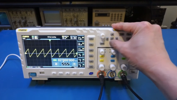
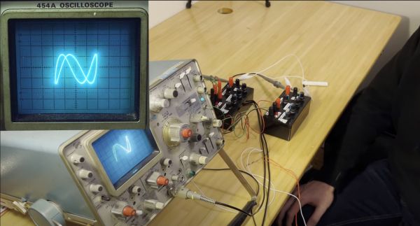
Generating interesting imagery on an analog oscilloscope is a fun activity enjoyed by many, with an excellent demonstration by [Henry Segerman] provided in a recent video which covers [Matthias Goerner]’s demonstration. Using the electron beam, shapes can be drawn onto the phosphor of the oscilloscope’s CRT — all without touching any digital circuitry. At the core are analog components like an operational amplifier integrator, multipliers and other elements.

With just a number of these simple components in a circuit, it’s possible to draw a wide variety of shapes, all by applying the appropriate trigonometric parameters. In addition to the drawing of shapes, it is also demonstrated how these analog signals can be used for an analog audio synthesizer, and finally the image displayed on the oscilloscope is captured on Kodak (Polaroid) instant film, making the entire generating, processing and capturing chain fully analog.

While we’d be the last to campaign against digital electronics, it is fascinating to consider just how much can be done with analog electronics and a bit of mathematics. We assume that everyone did pay attention during math classes, making this a perfect chance to use all that knowledge of trigonometry.

Continue reading “Drawing Knots On An Oscilloscope Using Analog Means”

A Pi Pico Oscilloscope

At the budget end of the oscilloscope range lie the so-called pocket ‘scopes. About the size of a deck of cards, they combine a microcontroller and an LCD screen to make an instrument with a bandwidth in the tens of kilohertz and a not-too-sparkling performance. They’re something of a toy, but then again, if all that’s needed is a simple ‘scope for audio frequencies, they make a passable choice in a small package. Now [jgpeiro] has made one which is light years ahead of the toy kits, using a Raspberry Pi Pico, a 100 MHz ADC, and an effort to design a better input circuit.

At its simplest this could be a straightforward op-amp and ADC circuit feeding the Pico, but instead it has multiple stages carefully designed to offer the full bandwidth, and with gain, offset, and trigger settings being set by a series of DAC chips under software control. This and the decent bandwidth make this a much more viable oscilloscope, and one we’d like to see further developed.

By comparison, we took a look at the best of the competition a few years ago.

A small green circuit board with a tiny OLED display

An Oscilloscope Trigger For Vintage Video Processors

Working on retro computers is rarely straightforward, as [ukmaker] recently found out while designing a new display interface. Their oscilloscope was having trouble triggering on the video signal produced by older video circuitry, so they created the Video Trigger for Retrocomputers.

The Texas Instruments TMS9918 video display controller was used across a range of 1980s game consoles and home computers, from the well-known ColecoVision to Texas Instruments’ own TI-99/4. Substantial retro computing heritage notwithstanding, the video output from this chip was (for reasons unknown) not quite compatible with the Hantek DSO1502P oscilloscope. And without a better understanding of the video signal, it was difficult to use the chip with newer TFT displays, being designed for CRT televisions with more forgiving NTSC tolerances.

Maybe a different scope would have solved the problem, but [ukmaker] had a feeling that the ‘scope needed an external trigger signal. The Video Trigger project uses a LM1881 sync separator to tease out the horizontal and vertical sync signals from the vintage video chip, with the output piped into an ATmega 328P. Along with a smattering of discrete components, the ATmega aids the user in selecting which line to frame a trigger on, and the slope of the horizontal sync signal to align to. A tiny OLED display makes configuration easy.

If this has piqued your interest, [ukmaker] also has a great write-up over on GitHub with all the gory details. Maybe it will help you in your next vintage computing caper. Having the right tool can make all the difference, like this homebrew logic meter for hobby electronics troubleshooting. Or if you want to know more about the mystical properties of analog NTSC video, we’ve covered that, too.

2022 Cyberdeck Contest: The Oscilloscope Deck

When [Jak_o_Shadows] Siglent Oscilloscope died, he didn’t just mourn the loss, he saw an opportunity. See, he had a Raspberry Pi 400 already set aside for a cyberdeck build, and he just scored a novel case. Most of the insides of the old scope came out, but the screen and control knobs live on in the new build. An HDMI-to-LVDS adapter brought the screen back to life, and the control knobs are a work-in-progress. Added to the case are some fun goodies, like a LimeSDR, connected to the old scope inputs. A PL2303 is wired to the serial port, making that functional, too. It’s a very nice touch that the build retains the original scope’s functions this way.

There’s plenty of 3d-printed goodness, like some internal brackets to hold things in place. The real star of the show is a 3d-printed hinge, holding the scope and Pi 400 together and making the whole package portable. There’s a neat tip, too, in that the Pi 400 has a huge integrated heat sync under the keyboard. It’s just a sheet of metal, so you can drill and tap it as mounting points. Cool!

This is a nifty build, and certainly a worthy deck for jacking-in to whatever you’re working on. And re-purposing an oscilloscope is a nice aesthetic. If [Jak_o_Shadows] can just get the front array of buttons and knobs working with his STM32, this will be a killer deck, the envy of console cowboys everywhere.

Balancing A Motor With An Oscilloscope

With all things in life, one must seek to achieve balance. That may sound a little like New Age woo-woo, but if you think it’s not literally true, just try tolerating a washing machine with a single comforter on spin cycle, or driving a few miles on unbalanced tires.

Anything that rotates can quickly spin itself into shrapnel if it’s not properly balanced, and the DIY power tools in [Matthias Wandel]’s shop are no exception. Recent upgrades to his jointer have left the tool a bit noisy, so he’s exploring machine vibrations with this simple but clever setup. Using nothing but a cheap loudspeaker and an oscilloscope, [Matthias] was able to characterize vibrations in a small squirrel-cage blower — he wisely chose to start small to validate his method before diving into the potentially dangerous jointer. There was quite a lot to be learned from the complex waveforms coming back from the transducer, analysis of which was greatly helped by the scope’s spectrum analyzer function. The video below shows the process of probing various parts of the blower, differentiating spectral peaks due to electrical noise rather than vibration, and actually using the setup to dynamically balance the fan.

We’d rate this as yet another handy shop tip from [Matthias], and we’ll be looking out for the analysis of his jointer. Want to do the same but you don’t have an oscilloscope? No problem — an earbud and Audacity might be all you need.

Continue reading “Balancing A Motor With An Oscilloscope”

Cheap Oscilloscope Is… Well… Cheap

We always enjoy watching [Kerry Wong] put an oscilloscope through its paces. His recent video is looking at a very inexpensive FNIRSI 1014D ‘scope that you can also find rebranded. You can usually find these for well under $200 at the usual places. Can you get a reasonable scope for that cost? [Kerry] has a list of issues with the scope ranging from short memory depth to low sensitivity. He did, however, like that it is USB powered so it can be operated from a common battery pack, which would make it truly floating.

The ‘scope looks like a lot of other inexpensive ‘scopes, but you can see some concessions to price. For example, the encoder knobs don’t have a push button function, making the scope more difficult to operate. While the specs are relatively modest, [Kerry] wasn’t sure the instrument was even living up to them.

Continue reading “Cheap Oscilloscope Is… Well… Cheap”

A FET Oscilloscope Probe For Higher Frequencies

It’s a problem that has dogged electronic engineers since the first electrons were coaxed along a wire: that measuring instruments can themselves disrupt the operation of a circuit. Older multimeters for example had impedances low enough to pull resistor values, thus our multimeters today have high-impedance FET inputs. [Christoph] faced it with his oscilloscope probe, its input capacitance was high enough to put unacceptable load on a crystal oscillator and stop it oscillating. He thus built a FET input probe for higher RF frequencies, and its construction is an accessible view of wideband RF instrumentation design.

The circuit is a very simple one using a dual-gate FET, but the interest comes in the PCB and screening can design to ensure good RF performance. Off-the-shelf cans have four sides, so to accommodate the circuit one wall of the can had to be removed. The end result is a tiny PCB with miniature co-ax connectors for power and signal, which when characterised was found to have a 1.3 GHz bandwidth and a very low input capacitance.

If the language of RF design is foreign to you, may we recommend [Michael Ossmann]’s talk at a Superconference a few years ago.