Soldering Glass And Titanium With Ultrasonic Energy

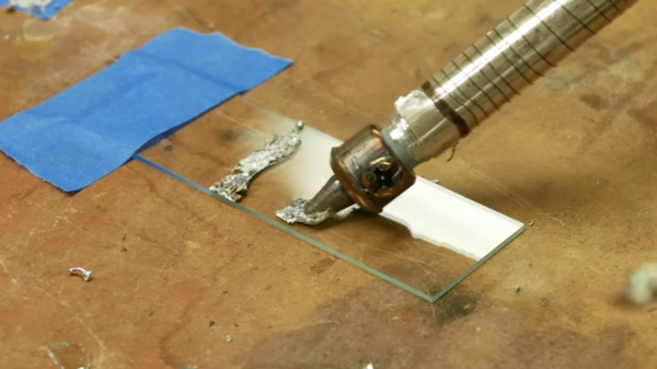
Ultrasonic soldering is a little-known technology that allows soldering together a variety of metals and ceramics that would not normally be possible. It requires a special ultrasonic soldering iron and solder that is not cheap or easy to get hold of, so [Ben Krasnow] of [Applied Science] made his own.

Ultrasonic soldering irons heat up like standard irons, but also require an ultrasonic transducer to create bonds to certain surfaces. [Ben] built one by silver soldering a piece of stainless steel rod (as a heat break) between the element of a standard iron and a transducer from an ultrasonic cleaner. He made his special active solder by melting all the ingredients in his vacuum induction furnace. It is similar to lead-free solder, but also contains titanium and small amounts of cerium and gallium. In the video below [Ben] goes into the working details of the technology and does some practical experimentation with various materials.

Ultrasonic soldering is used mainly for electrically bonding metals where clamping is not possible or convenient. The results are also not as neat and clean as with standard solder. We covered another DIY ultrasonic soldering iron before, but it doesn’t look like that one ever did any soldering.

Ultrasonic energy has several interesting mechanical applications that we’ve covered in the past, including ultrasonic cutting and ultrasonic welding.

Continue reading “Soldering Glass And Titanium With Ultrasonic Energy”

Simultaneous Soldering Station

Soldering irons are a personal tool. Some folks need them on the cool side, and some like it hot. Getting it right takes some practice and experience, but when you find a tip and temp that works, you stick with it. [Riccardo Pittini] landed somewhere in the middle with his open-source soldering station, Soldering RT1. When you start it up, it asks what temperature you want, and it heats up. Easy-peasy. When you are ready to get fancy, you can plug in a second iron, run off a car battery, record preset temperatures, limit your duty-cycle, and open a serial connection.

The controller has an Arduino bootloader on a 32u4 processor, so it looks like a ProMicro to your computer. The system works with the RT series of Weller tips, which have a comprehensive lineup. [Riccardo] also recreated SMD tweezers, and you can find everything at his Tindie store.

Soldering has a way of bringing out opinions from novices to masters. If we could interview our younger selves, we’d have a few nuggets of wisdom for those know-it-alls. If ergonomics are your priority, check out TS100 3D-printed cases, which is an excellent iron, in our opinion.

Digging Deep Into SD Card Secrets

To some, an SD card is simply an SD card, notable only for the amount of storage it provides as printed on the label. However, just like poets, SD cards contain multitudes. [Jason Gin] was interested as to what made SanDisk’s High Endurance line of microSDXC cards tick, so he set out to investigate.

Naturally, customer service was of no help. Instead, [Jason] started by scraping away the epoxy covering which hides the card’s test points. Some delicate soldering was required to hook up the test points to a breakout board, while also connecting the SD interface to a computer to do its thing. A DS Logic Plus signal analyzer was used to pick apart the signals going to the chip to figure out what was going on inside.

After probing around, [Jason] was able to pull out the NAND Flash ID, which, when compared to a Toshiba datasheet, indicates the card uses BiCS3 3D TLC NAND Flash. 3D NAND Flash has several benefits over traditional planar Flash technology, and SanDisk might have saved [Jason] a lot of time investigating if they’d simply placed this in their promotional material.

We’ve seen other similar hacks before, like this data recovery performed via test points. If you’ve been working away on SD cards in your own workshop, be sure to let us know!

Hackaday Podcast 070: Memory Bump, Strontium Rain, Sentient Solder Smoke, And Botting Browsers

Hackaday editors Elliot Williams and Mike Szczys bubble sort a sample set of amazing hacks from the past week. Who has even used the smart chip from an old credit card as a functional component in their own circuit? This guy. There’s something scientifically devious about the way solder smoke heat-seeks to your nostrils. There’s more than one way to strip 16-bit audio down to five. And those nuclear tests from the 40s, 50s, and 60s? Those are still affecting how science takes measurements of all sorts of things in the world.

Take a look at the links below if you want to follow along, and as always, tell us what you think about this episode in the comments!

Direct download (60 MB or so.)

Continue reading “Hackaday Podcast 070: Memory Bump, Strontium Rain, Sentient Solder Smoke, And Botting Browsers”

ReMarkable Tablet Scores A MicroSD Slot

There’s been a marked trend towards modern tablets and phones having fewer expansion options. It’s becoming rarer to find a microSD slot available, which can be particularly frustrating. For [davisr], this simply wouldn’t do, and they set about hacking their ReMarkable tablet.

A rotary tool was used to make a tidy slot for the microSD card.

The ReMarkable already has a set of pads for an SDHC interface on the main board, ready to go. Despite this, both hardware and software modifications are required to get things up and running. [davisr] started by soldering some wires to the main board, feeding them to a microSD socket, which was mounted on the edge of the tablet in a convenient nook. The case was then delicately modified to make a slot for cards to be inserted and removed. With this done, the kernel was then recompiled to enable support for the SDHC interface, and everything was up and running.

With the modification in place, [davisr] now has over 150GB of storage available, which should last for quite some time. Similar hacks are possible on other platforms, too. Even the Pi Zero can mount a second SD card with the right mods!


An SDR Transceiver The Old-School Way

Software-defined radios or SDRs have provided a step-change in the way we use radio. From your FM broadcast receiver which very likely now has single-application SDR technology embedded in a chip through to the all-singing-all-dancing general purpose SDR you’d find on an experimenter’s bench, control over signal processing has moved from the analogue domain into the digital. The possibilities are limitless, and some of the old ways of building a radio now seem antiquated.

[Pete Juliano N6QW] is an expert radio home-brewer of very long standing, and he’s proved there’s plenty of scope for old-fashioned radio homebrewing in an SDR with his RADIG project.  It’s an SDR transceiver for HF which does all the work of quadrature splitting and mixing with homebrewed modules rather than the more usual technique of hiding it in an SDR chip. It’s a very long read in a diary format from the bottom up, and what’s remarkable is that he’s gone from idea to working SDR over the space of about three weeks.

A block diagram of the N6QW SDR

So what goes into a homebrew SDR? Both RF preamplifier, filters, and PA are conventional as you might expect, switched between transmit and receive with relays. A common transmit and receive signal path is split into two and fed to a pair of ADE-1 mixers where they are mixed with quadrature local oscillator signals to produce I and Q that is fed to (or from in the case of transmit) a StarTech sound card. The local oscillator is an Si5351 synthesiser chip in the form of an SDR-Kits USB-driven module, and the 90 degree phased quadrature signals are generated with a set of 74AC74 flip-flops as a divider.

Running the show is a Raspberry Pi running Quisk, and though he mentions using a Teensy to control the Si5351 at the start of his diary it seems from the pictures of the final radio that the Pi has taken on that work. It’s clear that this is very much an experimental radio as it stands with wired-together modules on a wooden board, so we look forward to whatever refinements will come. This has the feel of a design that could eventually be built by many other radio amateurs, so it’s fascinating to be in at the start.

If I and Q leave you gasping when it comes to SDR technology, maybe we can help.

Thanks [Bill Meara N2CQR] for the tip!

Panadaptors Didn’t Start With SDRs

The must-have accessory on a modern all-singing, all-dancing amateur radio transceiver is a panadaptor. Inevitably driven by SDR technology, it’s a view of a band in the frequency domain, and it will usually be displayed as a “waterfall” giving a time dimension to see transmissions over a period.

[Bill Meara, N2CQR] reminds us that panadaptors are nothing new, indeed that they date back to the first half of the last century and don’t even need an SDR to work. And to prove it, he’s produced one for part of the 40-metre amateur band.

The principle behind an analogue panadaptor is simple enough, it’s a normal receiver whose local oscillator is given a linear periodic sweep over the desired frequency band and whose output drives the Y axis of an oscilloscope whose X axis is driven by the sweep. In [Bill]’s case the receiver is a BitX homebrew transceiver, and the swept local oscillator is provided by his Foeltech signal generator. A neat touch comes in the ‘scope being synchronised by triggering on a marker frequency at the bottom of the range being swept. He’s created a video showing it in action, which you can see below the break.

There are quite a few routes into making this type of simple spectrum analyser, indeed some of us have tried ti with TV tuners.

Continue reading “Panadaptors Didn’t Start With SDRs”