Robotic Laundry Line Reels You In

It may not be a laundry-folding robot, but this robotic launders line build by [Radical Brad Graham] is pretty neat. He has a 75-foot hanging laundry line from his house to a woodshed, and decided to roboticize it using some bits that were lying around. The result is a simple build that adds push-button control to pull the line back and forward, making it easier to hang everything out to dry. It’s a simple build, but [Brad] did a great job of documenting what he did and why, from mounting the posts that support the line to wiring up the control buttons.

Continue reading “Robotic Laundry Line Reels You In”

Dealing With Missing Pin Allocations

Blindsided by missing pin allocations? Perhaps you’re working on a piece of hardware and you notice that the documentation is entirely wrong. How can you get your device to work?

[Dani Eichhorn]’s troubles began when running an IoT workshop using a camera module. Prior to the work, no one had through to check if all of the camera modules ordered for the participants were the same. As it turns out, the TTGO T-CAM module had a number of revisions, with some even receiving a temperature/pressure sensor fixed on top of the normal board.

While the boards may have looked the same, their pin allocations were completely different.Changing the pin numbers wouldn’t have been difficult if they were simply numbered differently, but because the configurations were different, errors started to abound: Could not initialize the camera

As it turns out, even the LillyGo engineers – the manufacturers of the board – may have gotten a bit lost while working on the pin allocations, as [Eichhorn] was able to find some of the pins printed right onto the PCB, hidden behind the camera component.

To find information not printed on the board, a little more digging was required. To find the addresses of the devices connected to the I2C bus, running a program to find peripherals listening on the bus did the trick. This was able to print out the addresses of the SSD1306 OLED display driver and the microphone for the board at hand.

To find the pins of peripherals not printed on the PCB or hidden on the silkscreen, a GPIO scanner did the trick. This in particular worked for finding the PIR (passive infrared) motion sensor.

We picked up a few tips and tricks from this endeavor, but also learned that reverse-engineering anything is hard, and that there isn’t any one method for finding pin allocations when the documentation’s missing.

Make Your Own Plasma Cutter

Of all the tools that exist, there aren’t many more futuristic than the plasma cutter, if a modern Star Wars cosplay if your idea of futuristic. That being said, plasma cutters are a powerful tool capable of making neat cuts through practically any material, and there are certainly worst ways to play with high voltage.

Lucky enough, [Plasanator] posted their tutorial for how to make a plasma cutter, showing the steps through which they gathered parts from “old microwaves, stoves, water heaters, air conditioners, car parts, and more” in the hopes of creating a low-budget plasma cutter better than any on YouTube or from a commercial vendor.

The plasma cutter does end up working up quite an arc, with the strength to slice through quarter-inch steel “like a hot knife through butter”.

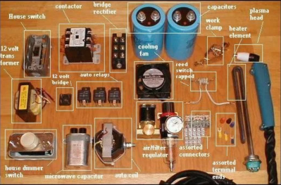
Its parts list and schematic divide the systems into power control, high current DC, low voltage DC, and high voltage arc start:

  • The power control contains the step down transformer and contactor (allows the DC components to come on line)
  • The high current DC contains the bridge rectifier, large capacitors, and reed switch (used as a current sensor to allow the high voltage arc to fire right when the current starts to travel to the head, shutting down the high voltage arc system when it’s no longer necessary)
  • The low voltage DC contains the power switch, auto relays, 12V transformer, 120V terminal blocks, and a terminal strip
  • The high voltage arc start contains the microwave capacitor and a car ignition coil

At the cutting end, 13A is used to cut through quarter-inch steel. Considering the considerably high voltage cutter this is, a 20 A line breaker is needed for safety.

Once the project is in a more refined state, [Plasanator] plans on hiding components like the massive capacitors and transformer behind a metal or plastic enclosure, rather than have them exposed. This is mainly for safety reasons, although having the parts exposed is evocative of a steampunk aesthetic.

In several past designs, stove coils were used as current resistors and a Chevy control module as the high voltage arc start. The schematic may have become more refined with each build, but [Plasanator]’s desire to use whatever components were available certainly has not disappeared.

Continue reading “Make Your Own Plasma Cutter”

How To Make A Living With Embedded Systems

One of the biggest dreams anyone has is to make a living doing what they love. For all hackers, makers, and DIYers with a passion for embedded systems, it may make sense initially to pursue embedded systems design as a possible career, but without so much information on the types of qualifications or steps needed to actually secure a job offer, it may seem daunting to try and break into the field.

YouTuber [iAyan Pahwa] currently works as an embedded software engineer, having been in the field for two years, with prior experience as a hobbyist working with microcontrollers, motors, and programming in the embedded domain. In this video, embedded below, he provides his take on what you need to know to get yourself that first job.

Continue reading “How To Make A Living With Embedded Systems”

Extreme Refurbishing: Amiga Edition

The last Amiga personal computer rolled off the assembly line in 1996, well over 20 years ago. Of course, they had their real heyday in the late 80s, so obviously if you have any around now they’ll be in need of a little bit of attention. [Drygol] recently received what looks like a pallet of old Amiga parts and set about building this special one: The Vampiric Amiga A500.

The foundation of this project was a plain A500 with quite a bit of damage. Corrosion and rust abounded inside the case, as well as at least one animal. To start the refurbishment, the first step was to remove the rust from the case and shields by an electrochemical method. From there, he turned his attention to the motherboard and removed all of the chips and started cleaning. Some of the connectors had to be desoldered and bathed in phosphoric acid to remove rust and corrosion, and once everything was put back together it looks almost brand new.

Of course, some other repairs had to be made to the keyboard and [Drygol] put a unique paint job on the exterior of this build (and gave it a name to match), but it’s a perfect working Amiga with original hardware, ready to go for any retrocomputing enthusiast. He’s no stranger around here, either; he did another extreme restoration of an Atari 800 XL about a year ago.

Fast Video Covers Coax Velocity Factor

We once saw an interview test for C programmers that showed a structure with a few integer, floating point, and pointer fields. The question: How big is this structure? The correct answer was either “It depends,” or “sizeof(struct x).” The same could be said of the question “What is the speed of light?” The flip answer is 186,282 miles per second, or 299,792,458 metres per second. However, a better answer is “It depends on what it is traveling in.” [KB9VBR] discusses how different transmission lines have different velocity factors and what that means when making RF measurements. A cable with a 0.6 velocity factor sees radio signals move at 60% of that 186,282 number.

This might seem like pedantry, but the velocity factor makes a difference because it changes the actual measurements of such things as dipole legs and coax stubs. The guys make a makeshift time domain reflectometer using a signal generator and an oscilloscope.

Continue reading “Fast Video Covers Coax Velocity Factor”

Tearing Down IKEA’S Sonos Speaker

There’s little better way to learn about a piece of electronics than by tearing it down. Taking a peek under the hood can reveal all manner of things about a device’s design, manufacturing, and origins. [This Does Not Compute] does a great job of doing just that, digging into the guts of IKEA’s Symfonisk speaker.

Symfonisk is a WiFi-enabled speaker, working with the Sonos ecosystem. Tearing down the device reveals some similarities to IKEA’s earlier Eneby speaker, with both devices sharing similar speaker drivers, apparently sourced from GGEC. However, upon digging deeper, it’s revealed that the Symfonisk has more in common with a speaker from another manufacturer entirely.

The video does a great job of not only investigating the manufacturing origins of the device, but breaking down the way it all works. This shows how the speaker relies on an Atheros WiFi-only chipset, thus explaining the lack of Bluetooth functionality, as well as discussing things like the neat solutions for cable management. Interestingly, the speaker uses a two-channel DAC and Class-D amplifier, but only operates in mono. Instead, the two channels are instead used to separately drive the tweeter and woofer, allowing EQ to be done in software on the main CPU, negating the need for analog crossover electronics.

It’s a teardown that would serve as a great primer for anyone considering building a piece of consumer electronics, but particularly those involved in the hi-fi space. To see how it was done way back when, perhaps try this 8-track teardown instead. Video after the break.

Continue reading “Tearing Down IKEA’S Sonos Speaker”