Baking is a wonderful pastime, as much an art as a science. [Alex] pursues the craft with plenty of vigor, and had built his very own dough sheeter to assist in his work. Unfortunately, the design had several flaws, and came out of a recent move rather the worse for wear. Growing tired of having to deal with dough of inconsistent thickness, he went back to the drawing board to whip up a new version (Youtube link, embedded below).
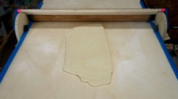
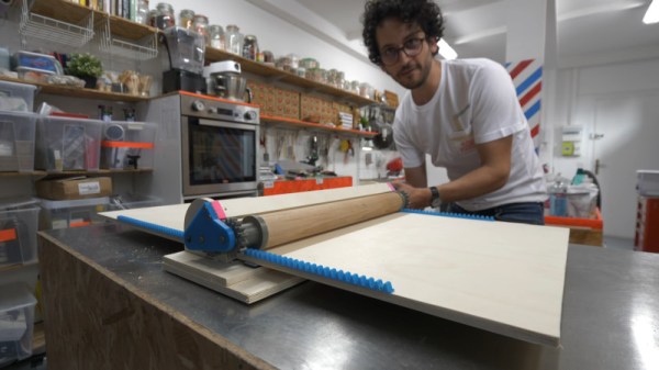
The core of the machine is a moving platform combined with a rolling pin, that can be set to a desired height to roll the dough into a set thickness. This is key to baking top-notch croissants, which [Alex] takes very seriously. His initial model used a table leg for a rolling pin, fitted with a threaded rod down the centre. This had significant issues with both runout, and uneven diameter across its length. Additionally, its frame had not held up after a recent move, and [Alex] was keen to start again.
The new model starts with attention paid to the basic engineering issues. The table leg is replaced with a professional-grade rolling pin, fitted with 3D-printed gears that accurately align the axis of rotation to the centre of the pin. A rack and pinion drive is also added to move the dough platform. Finally, a locking pin system is used to set the desired height of the dough.
It’s a useful project for the keen baker, and one that leans heavily on additive manufacturing methods. Producing such a tool in the years before 3D printers would have required significant effort to produce the required gears and mating components, so it’s impressive to see how easily something like this can come together these days. A hacker mindset can always be handy for baking – don’t forget, you can improve your bread crusts with steam! Video after the break.
Continue reading “The Quest For Perfect Croissants Via A DIY Dough Sheeter”


 Commuting through the urban sprawl of a 21st century city brings exposure to significant quantities of pollution. For a Medway Makers member that meant the Isle of Dogs, London, and a drive through the Blackwall Tunnel under the Thames. When you can taste the pollution in the air it’s evident that this isn’t the best environment to be in, but just how bad is it? Time to put together