When it comes to safes, mechanical design and physical layout are just as important as the electronic bits. If care isn’t taken, one element can undermine the other. That appears to be the case with this Amazon Basics branded biometric pistol safe. Because of the mechanical design, the fingerprint sensor can be overridden with nothing more than a thin piece of metal — no melted gummi bears and fingerprint impressions involved.
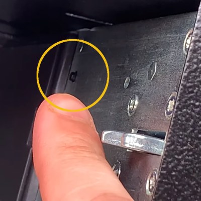
Small button used to register a new fingerprint. It can be reached by inserting a thin shim in the gap between the door and the frame while the safe is closed and locked.
[LockPickingLawyer] has a reputation for exposing the lunacy of poorly-designed locks of all kinds and begins this short video (embedded below) by stating that when attempting to bypass the security of a device like this, he would normally focus on the mechanical lock. But in this case, it’s far more straightforward to simply subvert the fingerprint registration.
This is how it works: the back of the front panel (which is inside the safe) has a small button. When this button is pressed, the device will be instructed to register a new fingerprint. The security of that system depends on this button being inaccessible while the safe is closed. Unfortunately it’s placed poorly and all it takes is a thin piece of metal slid through the thin opening between the door and the rest of the safe. One press, and the (closed) safe is instructed to register and trust a new fingerprint. After that, the safe can be opened in the usual way.
It’s possible that a pistol being present in the safe might get in the way of inserting a metal shim to hit the button, but it doesn’t look like it. A metal lip in the frame, or recessing the reset button could prevent this attack. The sensor could also be instructed to reject reprogramming while the door is closed. In any case, this is a great demonstration of how design elements can affect one another, and have a security impact in the process.
Whether you’re getting ready for work in the morning, or heading out on a camping trip in the woods, it’s nice to know what to expect when the weather rolls over the horizon. To keep abreast of things, [natethecoder] built a lamp system to stay across weather alerts.
A Raspberry Pi 3 acts as the heart of the system, with Node Red responsible for running the show. Querying the web every 5 minutes for updated weather data, it keeps track of weather alerts, as well as incoming snowfall. For a basic weather watch, a yellow lamp is lit, while there’s a red lamp for more serious warnings. A Christmas decoration serves as the indicator for snow. The lamps are all controlled by mains-rated solid state relays, making it easy to swap out the lamps for other devices if so desired down the track. There’s also a lamp test subroutine that fires on startup to ensure everything is working correctly.
We all use antennas for radios, cell phones, and WiFi. Understanding how they work, though, can take a lifetime of study. If you are rusty on the basic physics of why an antenna radiates, have a look at the very nice animations from [Learn Engineering] below.
The video starts with a little history. Then it talks about charges and the field around them. If the charge moves at a constant speed, it also has a constant electric field around it. However, if the charge accelerates or decelerates, the field has to change. But the field doesn’t change everywhere simultaneously.
If you’re looking for a fancy LED lamp, the Internet can provide in spades. There are all manner of flashy-this and glowing-that, often with wild and impressive designs made with high-end tools. However, when it came time to decorate the apartment, [thebigpotatoe] wanted to build something simple that anyone could attempt. From this, the Super Simple RGB WiFi Lamp was created.
The body of the lamp consists of a plank of wood. It may not sound like much, but thanks to a nifty design, it actually comes out looking remarkably stylish. The plank is fitted with aluminium angle on the back, and a strip of WS2812B LEDs are wrapped around the perimeter of the board. An ESP8266 NodeMCU is fitted to run the show, and powered from a mains supply to allow it to run all day.
The trick here is that the LEDs are mounted on the back of the board, where they are out of direct sight. The light from the LEDs is projected onto the wall the lamp is mounted on, giving a nice smooth effect without requiring any dedicated diffusers. There’s a series of animations coded in, which look great, particularly when the animations wrap around the end of the lamp.
It’s a great addition to the apartment’s feature wall, and goes to show that you don’t need world-beating crafting skills to make a great piece for your home. You can even go all out, and light your whole room this way. Video after the break.
[Starhawk] is a man with a problem. More accurately, he’s a man whose mother has a problem, but ultimately that ends up being the same thing. Her wide-format Canon printer recently stopped working after better than a decade of reliable service, and he wants to know why. Rather than spend the money on buying a new printer, he’s determined to find out if she’s been the victim of planned obsolescence by reverse engineering the Canon i9900 to see what makes it tick (or stop ticking, as the case may be).
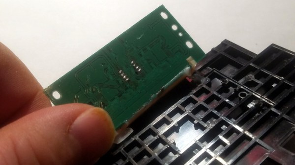
In the absence of any obvious hardware faults, [Starhawk] has suspicions that the machine’s QY6-0055 printhead has run over some internal “odometer” and simply turned itself off. We’ve all seen similar trickery at play when trying to use third party ink cartridges in our printers, so it’s certainly not outside the realm of possibility that the Canon i9900 is designed to reject heads once they’ve seen enough usage. Perhaps the biggest clue is that the QY6-0055 has a Seiko S93C56BR EEPROM on the board that’s keeping track of…something.
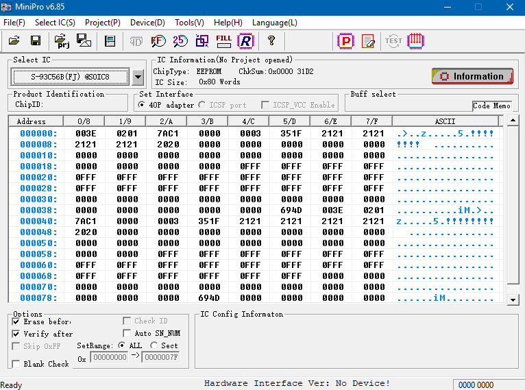
Right now, [Starhawk] is devoting his energies on trying to make sense of the data he pulled from the EEPROM using his TL866A programmer. But that’s no easy feat with a sample size of just one, which is why he’s looking for help. He’s hoping that other hackers with similar printers (and ideally ones that use the same QY6-0055 head) could submit their own EEPROM dumps and the community could get to work trying to decipher what’s stored on the chips. He’s really hoping that somebody at Canon might be willing to sneak him a couple tips on what he should be looking for, but at this point we think he’ll take whatever assistance he can get.
Now to be fair, there’s really no way to know definitively if there’s some flag stored on the EEPROM that’s keeping the printer from working. It could just be good old fashioned hardware failure, which would hardly be a surprise for a piece of consumer electronics from 2005. But even if the effort to understand the Canon’s EEPROM doesn’t get him any closer to a working printer, we still think it’s a fascinating example of real-world reverse engineering that’s worth it for the experience alone.
3D printers are great for rapid prototyping, but they’re not usually what you’d call… portable. For [Malte Schrader], that simply wouldn’t do – thus, the X-printer was born!
The X-printer is a fused-deposition printer built around a CoreXY design. Its party piece is its folding concertina-style Z-axis, which allows the printer to have a build volume of 160x220x150mm, while measuring just 300x330x105mm when folded. That’s small enough to fit in a backpack!
Getting the folding mechanism to work took some extra effort, with the non-linear Z-axis requiring special attention in the firmware. The printer runs Marlin 1, chosen for its faster compile time over Marlin 2. Other design choices are made with an eye to ruggedness. The aluminium frame isn’t as light as it could be, but adds much needed rigidity and strength. We’d love to see a custom case that you could slide the printer into so it would be protected while stowed.
At the end of August I made the trip to Hebden Bridge to give a talk at OSHCamp 2019, a weekend of interesting stuff in the Yorkshire Dales. Instead of a badge, this event gives each attendee an electronic kit provided by a sponsor, and this year’s one was particularly interesting. The RC2014 Micro is the latest iteration of the RC2014 Z80-based retrocomputer, and it’s a single-board computer that strips the RC2014 down to a bare minimum. Time to spend an evening in the hackerspace assembling it, to take a look!
It’s An SBC, But Not As You Know It!
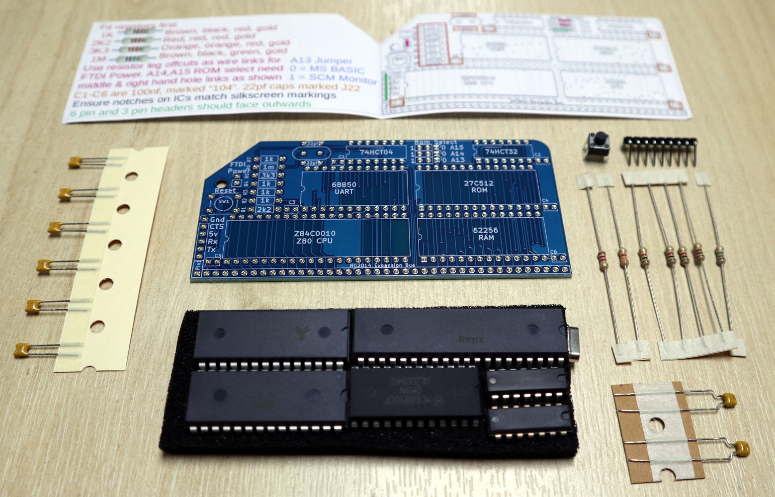
The kit contents
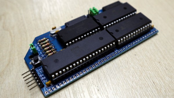
The kit arrives in a very compact heat-sealed anti-static packet, and upon opening was revealed to contain the PCB, a piece of foam carrying the integrated circuits, a few passives, and a very simple getting started and assembly guide. The simplicity of the design becomes obvious from the chip count, there’s the Z80 itself, a 6850 UART, 27C512 ROM, 62256 RAM, 74HCT04 for clock generation, and a 74HCT32 for address decoding. The quick-start is adequate, but there is also a set of more comprehensive online instructions (PDF) available.
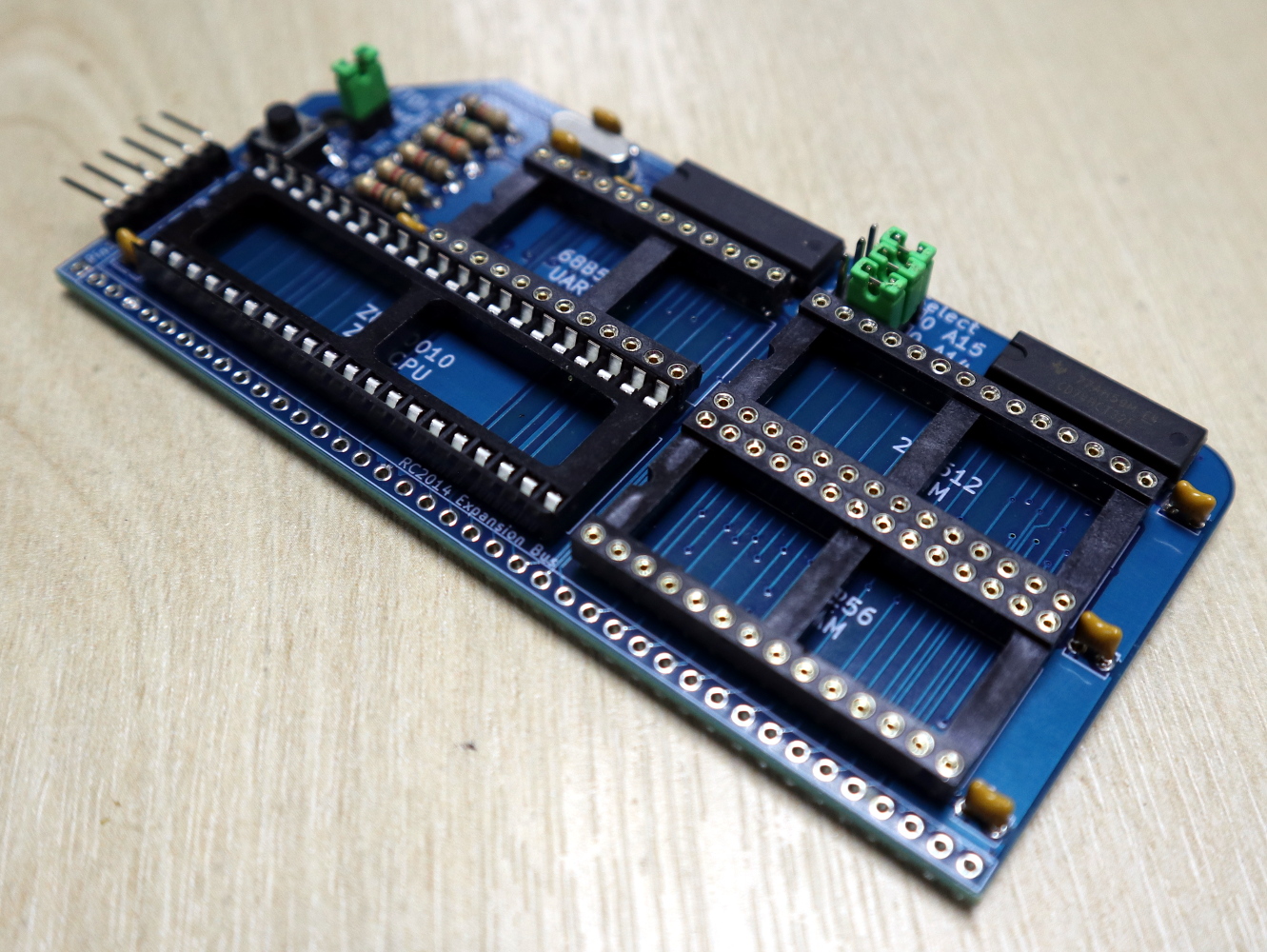
I added chip sockets and jumpers to my kit.
Assembly of a through-hole kit is hardly challenging, though this one is about as densely-packed as it’s possible to make a through-hole kit with DIP integrated circuits. As with most through-hole projects, the order you pick is everything: resistors first, then capacitors, reset button and crystal, followed by integrated circuits.
I’m always a bit shy about soldering ICs directly to a circuit board so I supplemented my kit with sockets and jumpers. The jumpers are used to select an FTDI power source and ROM addresses for Grant Searle’s ROM BASIC distribution or Steve Cousins’ SCM 1.0 machine code monitor, and the kit instructions recommended hard-wiring them with cut-off resistor wires. There was no row of pins for the expansion bus because this kit was supplied without the backplane that’s a feature of the larger RC2014 kits, but it did have a set of right-angle pins for an FTDI serial cable.
Your Arduino Doesn’t Have A Development Environment On Board!
Having assembled my RC2014 Mini and given it a visual inspection it was time to power it up and see whether it worked. Installing the jumper for FTDI power, I attached my serial cable and plugged it into a USB port.
A really nice touch is that the Micro has the colours for the serial cable wires on the reverse side of the PCB, taking away the worry of getting it the wrong way round. A quick screen /dev/ttyUSB0 115200 to get a serial terminal from a bash prompt, hit the reset button, and I was rewarded with a BASIC interpreter. My RC2014 Micro worked first time, and I could straight away give it BASIC commands such as PRINT "Hello World!" and be rewarded with the expected output.
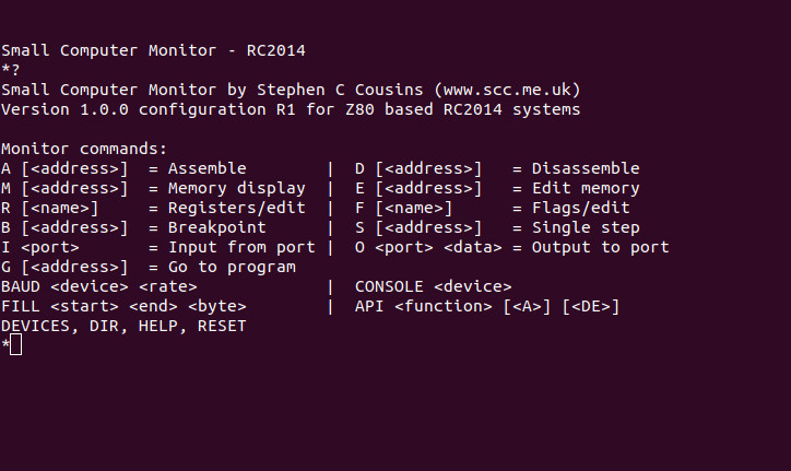
The SCM ROM monitor.
So I’ve built a little Z80 single board computer, and with considerably less work than that required for the fully modular version of the RC2014. Its creator Spencer tells me that the Micro was originally designed as a bargain-basement RC2014 as a multibuy for workshops and similar activities, being very similar to his RC2014 mini board but without provision for a Pi Zero terminal and a few other components. It lacks the extra hardware required for a more comprehensive operating system such as CP/M, so I’m left with about as minimal an 8-bit computer as it’s possible to build using parts available in 2019. My question then is this: What can I do with it?
So. What Can I Do With An 8-bit SBC?
My first computer was a Sinclair ZX81, how could it possibly compare this small kit that was a giveaway at a conference? Although the Sinclair included a black-and-white TV display interface, tape backup interface, and keyboard, the core computing power was not too far different in its abilities from this RC2014 Micro — after all, it’s the same processor chip. It was the platform that introduced a much younger me to computing, and straight away I devoured Sinclair BASIC and then went on to write machine code on it. It became a general-purpose calculation and computing scratchpad for repetitive homework due to the ease of BASIC programming, and with my Maplin 8255 I/O port card I was able to use it in the way a modern tech-aware kid might use an Arduino.
The RC2014 Micro is well placed to fill all of those functions as a BASIC and machine code learning platform on which to get down to the hardware in a way you simply can’t on most modern computers, and though the Arduino represents a far more sensible choice for hardware interfacing there is also an RC2014 backplane and I/O board available for the Micro’s expansion bus should you wish to have a go. Will I use it for these things? It’s certainly much more convenient than its full-sized sibling, so it’s quite likely I’ll be getting my hands dirty with a little bit of Z80 code. It’s astounding how much you can forget in 35 years!
The RC2014 Micro can be bought from Spencer’s Tindie store, with substantial bulk discounts for those workshop customers. If you want the full retrocomputer experience it’s a good choice as it provides about as simple a way into Z80 hardware and software as possible. The cost of simplicity comes in having no non-volatile storage and in lacking the hardware to run CP/M, but it has to be borne in mind that it’s the bottom of the RC2014 range. For comparison you can read our review of the original RC2014, over which we’d say the chief advantage of the Micro is its relative ease of construction.