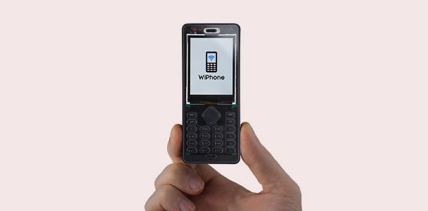
Based on the WiFi / Bluetooth wunderchip, clad in a polycarbonate frame, and looking like something that would be an amazing cell phone for 2005, the WiPhone is now available on Kickstarter.
We’ve seen the WiPhone before, and it’s an interesting set of features for what is effectively an ESP32 board with some buttons and a screen. It’s become something of a platform, with expansion daughterboards for LTE, LoRa, a camera, a Bus Pirate, and a programmable NFC/RFID doohickey. If you’ve longed for the day of big ‘ol Nokia brick phones, want to hack your phone, but don’t really care about actually having cellular connectivity, this is something that’s right up your alley.
Although the WiPhone looks like a usable product that was designed by someone with a sense of design, it still is Open Source. You can build your own, and there are dozens of expansion boards that will plug into the back of the WiPhone for prototyping, experimentation, and RGB Gaming LEDs. There’s no cellular modem on the WiPhone, though; for calls you’ll have to turn to SIP or VoIP apps.
Considering how difficult it is to source a cellular modem in small quantities and the desire for a cell phone that respects your Right to Repair, we’ve got to hand it to the WiPhone for creating something people want. It gets even better when you consider this looks more like a product than the 3D printed pieces of electronic cruft we usually see, and we’re happy to see this crowdfunding campaign just passed its goal and is completely funded.
While we’ve come a long way in terms of opening up the world of radio control to open source software, a good deal of the hardware itself is still closed up. You can flash a cheap RC transmitter with a community developed firmware, in fact there’s a decent chance that’s what it ships with, but the hardware itself is still an immutable black box. That might be fine if you’re just flying an RC plane or quadcopter, but what if you’ve got something a bit more advanced in mind?
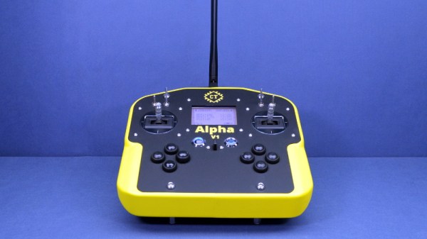
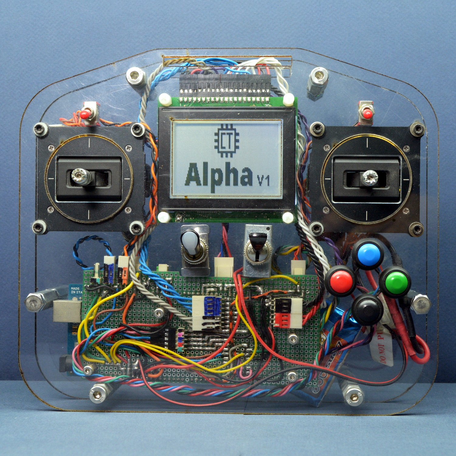
From his personal experience, [Alireza] found that traditional RC transmitters have their limits when you start using them for robotics. You’ll often want input schemes or devices which would never occur to the remote’s designers, and you’ll almost certainly want to have more channels and functions than the original hardware will allow. One of the big advantages with the Alpha V1 is that the front and back of the controller are simple acrylic panels, meaning you can easily cut openings or drill holes in them to add more hardware without having to deal with the (relatively) ergonomic shapes of a traditional transmitter.
Of course, that’s only one half of the equation. When you add new hardware, you’ll need to make the software aware of it. To that end, [Alireza] says he and his team have developed a library of adaptable firmware modules which should make it very easy to add in new components without having to get bogged down with software configuration. In fact, he says the goal is to allow the user to add new hardware to the Alpha V1 without requiring them to write a single line of code.
The Alpha V1 communicates at 2.4 GHz using either XBee or Murata DNT24 radios, and supports as many as 72 individual channels as well as two-way telemetry. If your requirements aren’t quite so high, we recently covered a significantly less intimidating attempt at building an open source RC transmitter that might suit your needs.
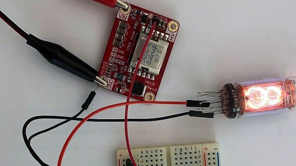
[Tony] built a high-efficiency power supply for Nixie tube projects. But that’s not what this post is about, really.
As you read through [Tony]’s extremely detailed post on Hackaday.io, you’ll be reading through an object lesson in electronic design that covers the entire process, from the initial concept – a really nice, reliable 170 V power supply for Nixie tubes – right through to getting the board manufactured and setting up a Tindie store to sell them.
[Tony] saw the need for a solid, well-made high-voltage supply, so it delved into data sheets and found a design that would work – as he points out, no need to reinvent the wheel. He built and tested a prototype, made a few tweaks, then took PCBWay up on their offer to stuff 10 boards for a mere $88. There were some gotchas to work around, but he got enough units to test before deciding to ramp up to production.
Things got interesting there; ordering full reels of parts like flyback transformers turned out to be really important and not that easy, and the ongoing trade war between China and the US resulted in unexpected cost increases. But FedEx snafus notwithstanding, the process of getting a 200-unit production run built and shipped seemed remarkably easy. [Tony] even details his pricing and marketing strategy for the boards, which are available on Tindie and eBay.
We learned a ton from this project, not least being how hard it is for the little guy to make a buck in this space. And still, [Tony]’s excellent documentation makes the process seem approachable enough to be attractive, if only we had a decent idea for a widget.
Ink! No matter the printer you’ve got, whether it be inkjet, laser or otherwise, it’s the consumables that will send you broke. At times, the cost of Hewlett-Packard black ink has exceeded the price per volume of human blood, and shareholders around the world have rejoiced.
As a retrocomputing reprobate, I have a personal dilection for printers of the vintage persuasion. My previous dalliances have involved fully fledged office copiers, but lately I’ve found myself tinkering with dot matrixes of a 1980s vintage. These workhorses are now reaching middle age, and as you’d expect, their ribbons are a little worse for wear after all this time.
Replacements are cheap enough for the most common printers, but shipping takes weeks and hackers are an impatient bunch. Plus, if you’ve got one of the more obscure models, it’s unlikely you’ll find a fresh cart just sitting on the shelf. It was these factors that spurred my good friend [Cosmos2000] and I into action.
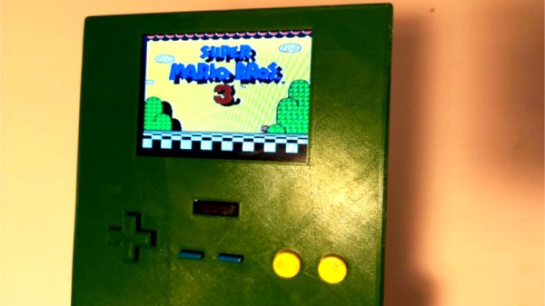
Emulation of classic consoles has long been a solved problem. It’s now possible to run thousands of vintage games on a computer the size of a stick of gum, and to do so with all the benefits emulation brings. [M-Parks] isn’t the biggest fan, however – and decided to build a slimline NES handheld instead. The goal was to produce a portable NES in as compact a package as possible.
Things have come a long way in the handheld console modding scene in the last ten years. 3D printing has largely replaced vacuum forming, and it’s no different here. [M-Parks] modeled up a case and sent it off to be 3D printed in PLA, somewhat mimicking the general layout of the original Game Boy. It’s a little larger, but given that it accepts full-size original NES carts, it can only be so small.
A Retro-bit NES-on-a-chip console was used to provide the motherboard and cartridge connector for the build. Rounding this out is a power supply from Adafruit, an LM386 audio amplifier, as well as a digital volume control which is a nice touch.
While such a build may sound daunting to the absolute beginner, all it takes is a soldering iron, some hot glue, and a willingness to have a go. There’s nothing wild or groundbreaking about this build, but to dwell on that would be missing the point. [M-Parks] now has a portable NES to play on those long train rides, and learned some great skills doing it – a solid result for any project!
This is the 2019 Hackaday Prize, the worldwide hardware design contest focused on product development. We know you can build a working prototype, and we still want to see you do that. But a great idea should have reach beyond your own workshop. This year’s Hackaday Prize is about taking your product across the finish line, from concept to design for manufacture.
Prizes to Jump Start Your Product
$125,000 and a Supplyframe DesignLab Residency await the Best Product winner. There are five focus categories this year, with the winner of each receiving a $10,000 prize. And to help encourage those early beginnings, we have another $10,000 in seed funding set aside which means up to $500 for each of the top 20 entries who get in and gather those “likes” before June first.
There are a few areas of focus you should have in mind as you work on your products. These are Concept, Design, Production, Benchmark, and Communication. All entries are eligible to receive prizes related to these, and in addition to the $50,000 we mentioned above for the winner in each area, we have another $3,000 for each set aside to recognize an honorable mention.
Something amazing happened thirty years ago. A core of very motivated hackers took on the mantle of design, software, and even business skill, to build the computers that thrust us into a new information age. As these machines matured, a wave of software engineers picked up that torch, themselves embracing product and design thinking to accelerate the startup craze to new levels, again changing the world.
Ask yourself where we are right now. What are the hot new startups? The buzz now is all about billion dollar valuation but where is the substance? What we really need are the scrappy hackers who have a flag to plant to change the world. We’ve mistakenly been waiting for software companies to use their special sauce to lead a hardware renaissance, but instead it feels like we’re solving more and more trivial problems — where are the world-changers?
This is the hunger behind the 2019 Hackaday Prize. Three decades later, it is time for Hardware Engineers to be recognized as Innovators and leaders again. This is the call for the hardware community to come together, share knowledge, acquire new skills, and embark on a journey that uses the technological raw materials at our fingertips to invent the solutions that really matter. Make the idea and the execution happen now, and that enormous valuation will follow. Now is the time to change the world, you are the hackers who will do it, and this time around hardware will be leading the charge.
Improvisation, Mentorship, and Your Ability to Do Everything
We know you can build a working prototype of just about anything. But just like the creators of the Commodore, the Sinclair, Amiga, Apple, and Atari, you need to be more than a hardware designer. You need to know your users like you know yourself. You need an eye for industrial design — each of the machines mentioned above are iconic by how they look and not just by how they work. People behind these products knew what they were up against, and chose to make them stand-out designs in terms of performance, price, and how they fit into our lives.
You don’t have every skill necessary to make a great leap forward in every one of these areas — nobody does. But with the right community around you, you will learn some of them and find collaborators for the rest. Throughout the 2019 Hackaday Prize we’ll be pushing everyone to step past where you think your skills end, to learn what makes a product great, what makes it loved by the end user, and what makes it feasible to follow through to the end of the rainbow.
Get in early and take part in Prize demo days. Get matched up with world-class mentors and work with them in a masterclass situation from which everyone can learn. Show off your work and you’ll attract good ideas and good people. This is the Homebrew Computer Club of the new millennium. You’re going to find inspiration (and become the inspiration!) from everyone in the club. You’re going to riff on the breakthroughs of others, and together we’re all going to lead that Hardware Renaissance.
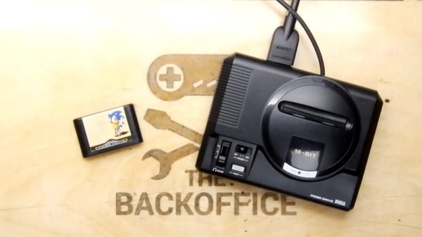
Miniature game consoles are all the rage right now. Many of the big names in gaming are releasing their own official “mini” versions of their classic machines, but naturally we see plenty of DIY builds around these parts as well. Generally they’re enclosed in a 3D printed model of whatever system they’re looking to emulate, but as you might expect that involves a lot of sanding and painting to achieve a professional look.
But for SEGA Genesis (or Mega Drive as it was known outside the US) fans, there’s a new option. A company by the name of Retro Electro Models has released a high-fidelity scale model of SEGA’s classic console, so naturally somebody hacked it to hold a Raspberry Pi. Wanting to do the scale detailing of the model justice, [Andrew Armstrong] went the extra mile to get the power button on the front of the console working, and even added support for swapping games via RFID tags.
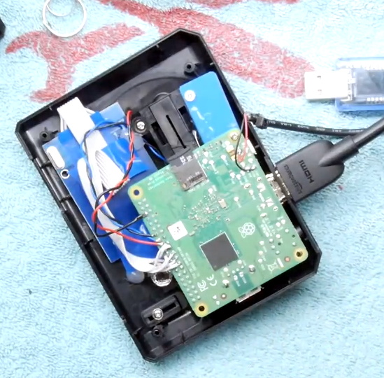
[Andrew] uses the Raspberry Pi 3 A+ which ended up being the perfect size to fit inside the model. Fitting the Pi Zero would have been even easier, but it lacks the horsepower of its bigger siblings. The RFID reader is connected to the Pi over SPI, and the reed switch used to detect when the power switch has been moved is wired directly to the GPIO pins. The system is powered by a USB cable soldered directly to Pi’s PCB and ran out a small hole in the back of the case.
For input, [Andrew] is using a small wireless keyboard that includes a touch pad and gaming controls. Unfortunately, it has a proprietary receiver which had to be integrated into the system. In a particularly nice touch, he used snipped off component leads to “wire” the receiver’s PCB directly to the pins of the Pi’s USB port. Not only does it look cool, but provides a rigid enough connection that he didn’t even need to glue it down to keep it from rattling around inside the case. Definitely a tip to keep in the back of your mind.
The software side of this project is about what you’d expect for an emulation console, though with the added trickery of loading games based on their RFID tag. At this point [Andrew] only has a single “cartridge” for the system, so he simply drops the tags into the cartridge slot of the console to load up a new title. It doesn’t look like Retro Electro Models is selling loose cartridges (which makes sense, all things considered), so there might still be a job for your 3D printer yet if you want to have a library of scale cartridges to go with your console.