Water wells are simple things, but that doesn’t mean they are maintenance-free. It can be important to monitor water levels in a well, and that gets complicated when the well is remote. Commercial solutions exist, of course, but tend to be expensive and even impractical in some cases. That’s where [Hans Gaensbauer]’s low-cost, buoyancy-based well monitor comes in. An Engineers Without Border project, it not only cleverly measures water level in a simple way — logging to a text file on a USB stick in the process — but it’s so low-power that a single battery can run it for years.
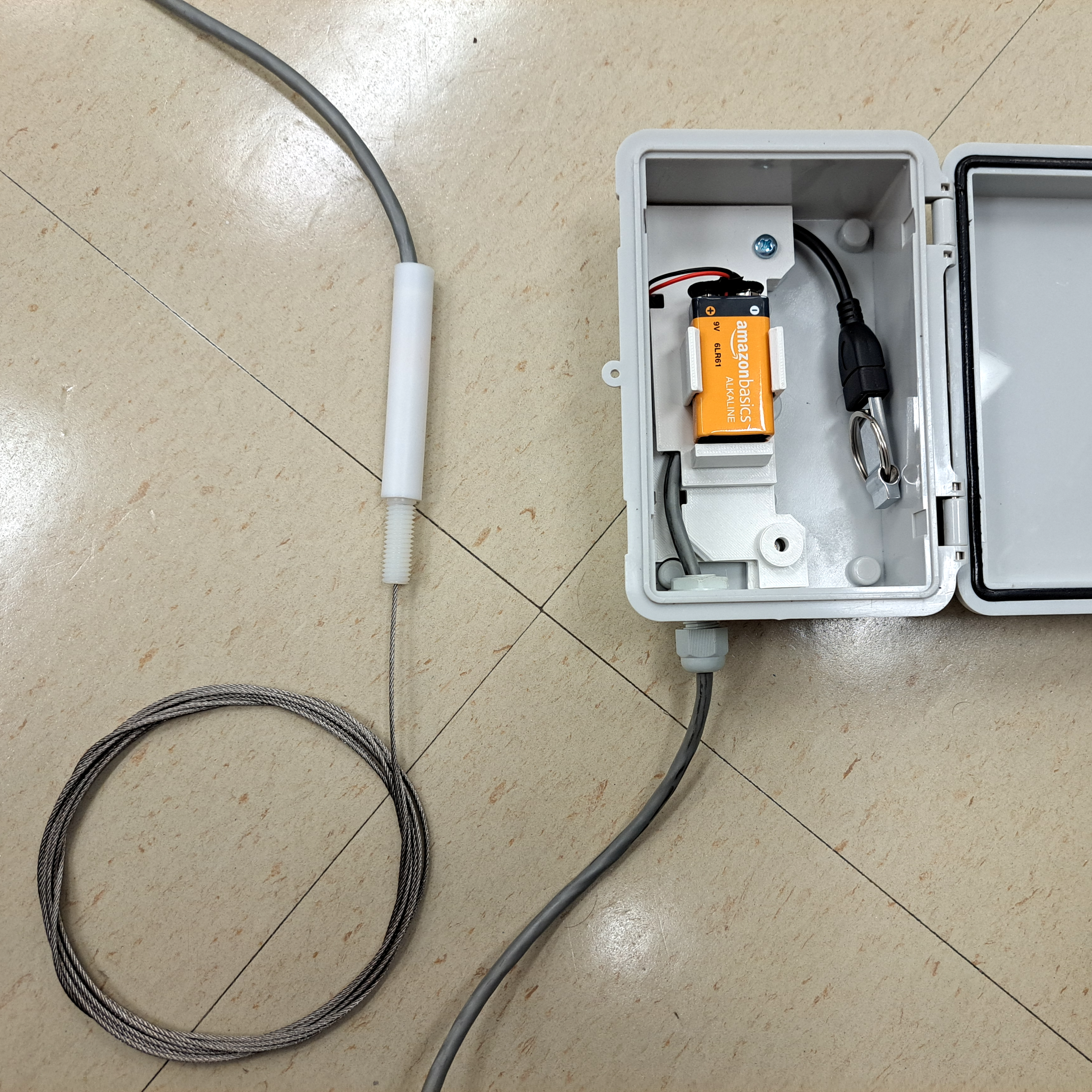
The monitor [Hans] designed works in the following way: suspend a length of pipe inside the well, and attach that pipe to a load cell. The apparent weight of the pipe will be directly proportional to how much of the pipe is above water. The fuller the well, the less the pipe will seem to weigh. It’s very clever, requires nothing to be in the well that isn’t already water-safe, and was designed so that the electronics sit outside in a weatherproof enclosure. Cost comes out to about $25 each, which compares pretty favorably to the $1000+ range of industrial sensors.
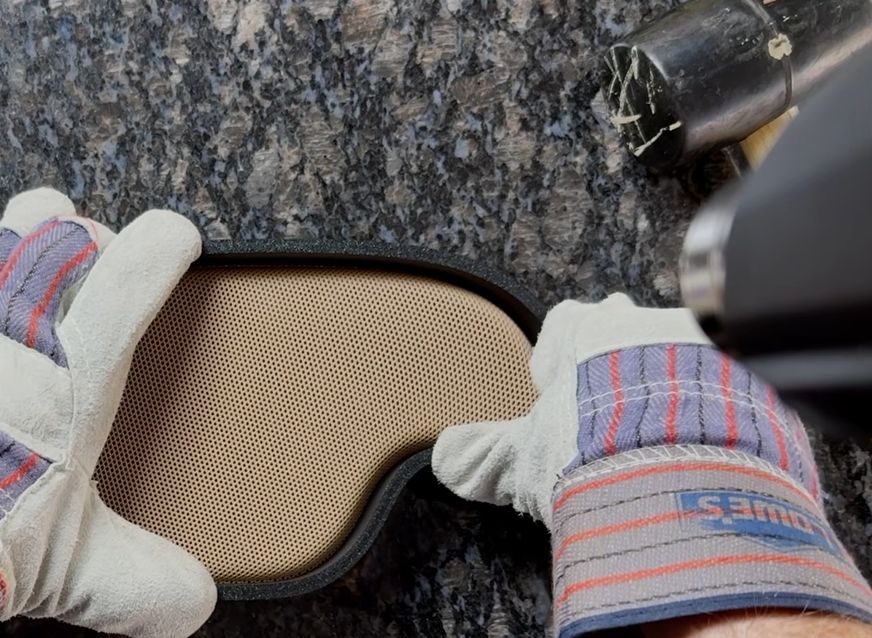
The concept is clever, but it took more that that to create a workable solution. For one thing, space was an issue. The entire well cap was only six inches in diameter, most of which was already occupied. [Hans] figured he had only about an inch to work with, but he made it work by designing a custom load cell out of a piece of aluminum with four strain gauges bonded to it. The resulting sensor is narrow, and sits within a nylon and PTFE tube that mounts vertically to the top of the well cap. Out from the bottom comes a steel cable that attaches to the submerged tube, and out the top comes a cable that brings the signals to the rest of the electronics in a separate enclosure. More details on the well monitor are in the project’s GitHub repository.
All one has to do after it’s installed is swap out the USB stick to retrieve readings, and every once in a long while change the battery. It sure beats taking manual sensor readings constantly, like meteorologists did back in WWII.