We all know the feeling of an idea that sounded great when it was rattling around in our head, only to disappoint when we actually build the thing. It’s a natural consequence of trying new stuff, and when it happens, we salvage what we can and move on, hopefully in wisdom.
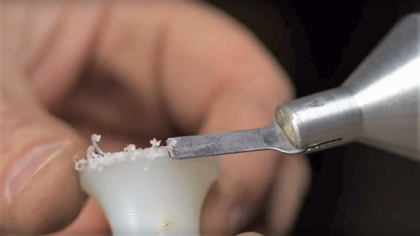
The thing that at least semi-defeated [This Old Tony] was an attempt to build an ultrasonic cutter, and it didn’t go well. Not that any blood was shed in the video below, although there seemed like there would be the way [Old Tony] was handling those X-Acto blades. His basic approach was to harvest the transducer and driver from a cheap ultrasonic cleaner and retask the lot into a tool to vibrate a knife rapidly enough to power it through tough materials with ease.
Spoiler alert: it didn’t work very well. We think the primary issue was using a transducer that was vastly underpowered compared to commercial (and expensive) ultrasonic cutters, but we suspect the horn he machined was probably not optimized either. To be fair, modeling the acoustic performance of something like that isn’t easy, so we can’t expect much. But still, it seems like the cutter could have worked better. Share your thoughts on how to make version 2.0 better in the comments.
The video is longish, but it’s as entertaining as any of [Old Tony]’s videos, and packed full of incidental gems, like the details of cavitation. We enjoyed it, even if the results were suboptimal. If you want to see a [This Old Tony] project that really delivers, check out his beautiful boring head build.
Continue reading “Fail Of The Week: The Little Ultrasonic Knife That Couldn’t”