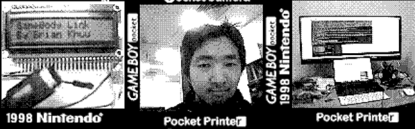
[Brian Khuu] bought a few Game Boy cameras on the Internet and found that they still had pictures on them from the previous owners. The memory in the camera has a backup battery and if that battery dies, the pictures are history, so he decided to mount a rescue operation.
He knew the protocol for how the Game Boy talked to the companion pocket printer was available, so he used an Arduino and a Web browser to extract the photos. The resulting code is on GitHub if you want to save your pictures. Although [Brian] didn’t have to crack the protocol, he does offer a good explanation of it. There’s even some sniffed displays. The Arduino does all the communications and fools the game into thinking it is the companion printer. However, it simply streams the data out and a Javascript decoder handles the actual decoding. In fact, in the blog post, you can enter data, click a button, and see the resulting Game Boy picture.
It works, but [Brian] did run into a few problems. For one thing, the devices don’t seem to use any flow control so he had no choice but to keep up with the Game Boy. Also, there is a CRC he could not correctly decode. However, the pictures look good — well, as good as Game Boy pictures look, at least. So he did get results.
[Tobias Kuhn] and a handful of colleagues at his workplace built Crystal Signal Pi, a Raspberry Pi based low-cost alternative for a notification device that provides visual, audio and network warnings about server problems. [Tobias] works for a Japanese company where it is critical for their servers to keep humming nicely all the time. Any emergencies or error conditions must be broadcast immediately so the technicians can fix it ASAP. Network enabled warning light stalks are used to provide these alerts. A local company produces a series of indicator and hazard warning lights which are colloquially called as Keiko-chan. These are similar to the hazard warning tower lights commonly fixed on machines on factory floors or many kinds of vehicles such as fork lifts. The Kieko-chans add a few bells and whistles making them more suitable for use in the server data centre — a Gigabit LAN port for wired networks and a USB port for WiFi modules. So, besides visual and audio warnings, it can also transmit messages over the network to alert the maintenance folks. Using this commercial solution should not have been a problem were it not for their rather hefty price tag of almost $500 per pop.
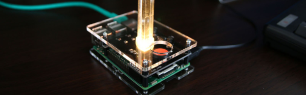
So [Tobias] decided to build his own warning lights based around the Raspberry Pi. After two rounds of prototypes, a simple HAT was designed that could be plugged in to a Pi. Details of the hardware are sketchy, but it’s simple enough to figure out. The part list consists of a PLCC-6 style RGB LED, three transistors to drive the three LED pins, a voltage regulator with a couple of electrolytic capacitors and a large push button. A simple acrylic case, and an acrylic cylinder mounted on top of the RGB LED creates a nice edge lit effect for the indicator.
The code for the Crystal Pi is hosted on Github, and includes handy scripts to make installation easy. Once installed, the Crystal Pi can be accessed and controlled either through a web-based GUI or via the API. There are some more interesting features already implemented or scheduled for later, so do check out the blog and the repository for more. Check out the video below to see the Crystal Pi in action.
There are a lot of things to like about [BoneConstructor]’s Skelly the skeleton robot project. Note that we said, “project”. That’s because not only does the robot work well and is built well, but the journey he took to make it contains steps we’ve all taken ourselves. We can say that with confidence since it’s his first, and we’ve all had those.
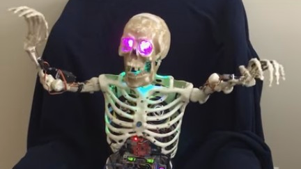
Skelly started life as a skeleton sitting in [BoneConstructor]’s antique race car at local car shows. Its eyes lit up and it made a moaning sound, which didn’t always work right. From there came lessons learned with head and arm servos, followed by problems with a PS2 remote and a control board. When he realized he’d have to write his own code, he was stymied by his lack of programming skills. But then he found Visuino, which as you can guess from the name is a visual way to program Arduinos, mostly consisting of drag-and-drop. From there on, the path was smoother, if not completely linear.
Rather than rapidly burn through servos by mounting the bones directly to the servo arms, he fitted bearings into the bone sockets, put the limbs on shafts through those bearings, and used pusher rods connected to the servo arms to turn those shafts. It’s no wonder the arms work so well. He took that sturdy and resilient approach with the wrists and neck too. He even made its right foot able to tap in tune with the music.
And from there we begin to understand some of the method to his madness. Check out the videos below, and on his Hackaday.io page and you’ll see how wonderfully Skelly moves to the music. It even took a moment for us to realize he wasn’t actually playing the piano. But best of all, we like how he rocks out to AC/DC’s Shoot To Thrill (Iron Man 2 Version). We’re really impressed by how well those robot arms hold up given that this is a first robot.
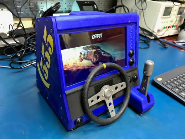
The idea was to build the smallest possible computer than can run SteamOS and fit inside of a cabinet printed on a Prusa clone. At first, [Daniel] tried driving a MinnowBoard around. The frame rate was atrocious, so he switched to an ASUS mini-STX board and went from there.
The printed steering wheel and throttle are both analog inputs—each uses a 10kΩ pot connected to a Pimoroni PiCade controller. We love [Daniel]’s lo-tech way of using rubber bands to self-center them. We also love the post-processing he did on the steering wheel to give it that just-right grippy feel (it’s Plasti-Dip rubber paint), because it looks fantastic.
The lovely blue cabinet is an homage to [Daniel]’s Dirt Rally destroyer of choice, the rally blue ’95 Subaru Impreza. He had an arduous print/sand/prime/paint plan all worked out for the prototype, but ultimately printed the parts in different colors to get the look right. [Daniel] went through four different blue filaments alone before he was satisfied.
Motor around the break for a quick walk around the completed cabinet, and park it for the teaser video that scored [Daniel] a swag bag from the Dirt Rally devs through the magic of social media. Now that it’s cold and flu season in the northern hemisphere, maybe you’d prefer to play driving games without touching anything.
The holiday season is full of many sounds; walking through your neighborhood on a winter night you may hear time-honored songs, the tinkling of glasses, and the laughter of good company. But if the chilly wind also brings to your ear the panicked sounds of screaming children, you may have wandered a bit to close to [Tyler Garner]’s house.
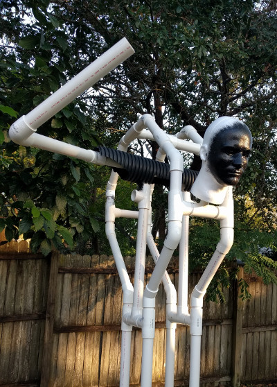
Rather than old Saint Nick or a couple of reindeer, [Tyler] decided to top the roof of his home with a disturbingly well done rendition of everyone’s favorite��Austro-Bavarian goat-demon, Krampus. While he did finish the build off with a store-bought Krampus mask, every other component was made with about a 60/40 ratio of hardware to craft store scores. While your holiday decorations this year may not include any spawns of hell, the general construction techniques and resourcefulness [Tyler] shows in this build may come in handy when Halloween rolls around again.
The “skeleton” of Krampus is made up of PVC pipes and fittings mounted on an MDF base. Not only do the PVC fittings make it easy to recreate the rough anatomy of a humanoid figure, but if you don’t glue them all together, you can take it apart later for storage. We might have gone with something a little heartier than MDF for the base, but at least [Tyler] added a few pieces of galvanized pipe at the bottom to give it a little weight down low.
Things start to get interesting when [Tyler] adds sections of drainage pipe to his PVC skeleton to give it a more girth, as he was finding the bare PVC didn’t have a realistic presence when the robes were thrown over them. [Tyler] also uses expanding spray foam to soften up areas such as the hunched back, which may look messy but has the dual advantages of being cheap and fast.
The figure’s robes are made up of a patchwork of burlap, waterproofed with a spray on liner intended for pickup truck beds. With the application of red and black spray paint and the customary white fringe, it really nails the look.
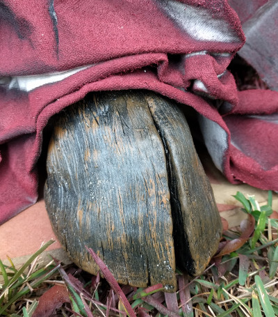
A particularly nice detail is the hoof peeking out from beneath the robes, which [Tyler] made out of painted air-dry clay. It’s an awesome detail, though almost impossible to see once Krampus is mounted on the roof. Maybe it’s just us, but we think putting so much effort into a nearly hidden feature of a project is the true mark of a master craftsman; this is a secret little hoof that [Bob Ross] himself would be proud of.
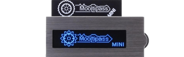
Mathieu Stephan is an open source hardware developer, a Tindie seller who always has inventory, a former Hackaday writer, and an awesome all-around guy. One of his biggest projects for the last few years has been the Mooltipass, an offline password keeper built around smart cards and a USB interface. It’s the solution to Post-It notes stuck to your monitor and using the same password for all your accounts around the Internet.
The Mooltipass is an extremely successful product, and last year Mathieu launched the Mooltipass Mini. No, it doesn’t have the sweet illuminated touch-sensitive buttons, but it is a bit cheaper than its big brother and a bit more resistant to physical attacks — something you want in a device that keeps all your passwords secure.
Mathieu didn’t build the Mooltipass alone, though. This is an Open Source project that has developers and testers from around the globe. It may have started off as a Hackaday Post, but now the Mooltipass has grown into a worldwide development team with contributors across the globe. How did Mathieu manage to pull this off? You can check out his talk at the 2017 Hackaday Superconference below.
Printed circuit boards are a fundamental part of both of commercial electronic equipment and of the projects we feature here on Hackaday. Many of us have made our own, whether done so from first principles with a tank of etchant, or sent off as a set of Gerbers to a PCB fab house.
To say that the subject of today’s Retrotechtacular is the manufacture of printed circuit boards might seem odd, because there is nothing archaic about a PCB, they’re very much still with us. But the film below the break is a fascinating look at the process from two angles, both for what it tells us about how they are still manufactured, and how they were manufactured in 1969 when it was made.
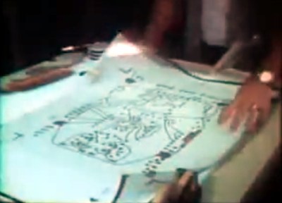
Board artwork laid out at four-times actual size
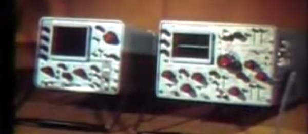
Tektronix were as famous for the manufacturer of particularly high quality oscilloscopes back then as they are now. The Tektronix ‘scopes of the late 1960s featured several printed circuit boards carrying solid-state electronics, and were manufactured to an extremely high standard. The film follows the manufacturing process from initial PCB layout to assembled board, with plenty of detail of all production processes.
In 2017 you would start a PCB design in a CAD package, but in 1969 the was incredibly manual. Everything was transcribed by hand from a paper schematic to transparent film. Paper mock-ups of component footprints four times larger than actual size are placed on a grid, and conductors drawn in pencil on an overlaid piece of tracing paper. Then the pads and pattern of tracks are laid out using black transfers and tape on sheets of film over the tracing paper, one each for top and bottom of the board. A photographic process reduces them to production size onto film, from which they can be exposed and etched in the same way that you would in 2017.
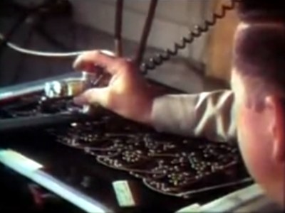
Pantograph drilling machine uses a manually moved styuls on a template to drill six boards at once
Most of the physical process of creating a PCB has not changed significantly since 1969. We are shown the through-plating and gold plating processes in detail, then the etching and silkscreening processes, before seeing component installation and finally wave soldering.
What are anachronistic though are some of the machines, and the parts now robotised that were done in 1969 by hand. The PCB drilling is done by hand with a pantograph drill for small runs, but for large ones a fascinating numerically-controlled drilling rig is used, controlled by punched tape without a computer in sight. Component placement is all by hand, and the commentator remarks that it may one day be done by machine.
The film remains simultaneously an interesting look at PCB production and a fascinating snapshot of 1960s manufacturing. It’s probable that many of the Tek ‘scopes made on that line are still with us, they’re certainly familiar to look at from our experience at radio rallies.