If you stand outside on a clear night, can you see the Milky Way? If you live too close to a conurbation the chances are all you’ll see are a few of the brighter stars, the full picture is only seen by those who live in isolated places. The problem is light pollution, scattered light from street lighting and other sources hiding the stars.
The view of the Milky Way is a good analogy for the state of the radio spectrum. If you turn on a radio receiver and tune to a spot between stations, you’ll find a huge amount more noise in areas of human habitation than you will if you do the same thing in the middle of the countryside. The RF noise emitted by a significant amount of cheaper modern electronics is blanketing the airwaves and is in danger of rendering some frequencies unusable.
![Can these logos really be trusted? By Moppet65535 (Own work) [CC BY-SA 3.0], via Wikimedia Commons](https://hackaday.com/wp-content/uploads/2016/06/fcc-ce-logos.jpg?w=400)
This situation has prompted the FCC Technological Advisory Council to investigate any changes to the radio noise floor to determine the scale of the problem. To this end they have posted a public notice (PDF) in which they have invited interested parties to respond with any evidence they may have.
We hope that quantifying the scale of the RF noise problem will result in some action to reduce its ill-effects. It is also to be hoped though that the response will not be an ever-tighter set of regulations but greater enforcement of those that already exist. It has become too easy to make, import, or sell equipment made with scant regard to RF emissions, and simply making the requirements tougher for those designers who make the effort to comply will not change anything.
This is the first time we’ve raised the problem of the ever-rising radio noise floor here at Hackaday. We have covered a possible solution though, if stray RF is really getting to you perhaps you’d like to move to the National Radio Quiet Zone.

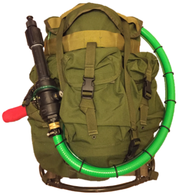 If you want to see how a project should be documented, look no further than [Tim]’s forum posts over at WaterWar.net. From the insanely detailed BOM with catalog numbers and links to supplier websites, to scads of build photos with part number callouts, to the finely detailed build instructions, [Tim] has raised the stakes for anyone that documents any kind of build.