Welcome to the 100th Hacklet! This has been a huge week for Hackaday, as we launched The 2016 Hackaday Prize. We’ve invited you to change the world. Hackers, makers, and engineers have already answered the call, with nearly 200 entered projects! What better way to celebrate our 100th Hacklet than taking a look at a few of these early entrants?
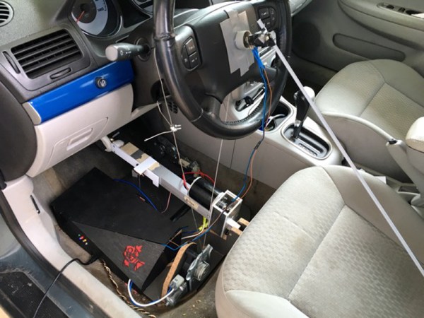
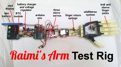 We start with [Patrick Joyce] and Raimi’s Arm – Bionic Arm for Kids. Raimi was born with an arm which ends just below the elbow. She’s still a kid – and growing, which means she will quickly grow out of any prosthetic. This has placed bionic arms out of her reach. [Patrick] saw a plea from Raimi’s father for help. 3D printed arms for the disabled are a thing, but [Patrick] couldn’t find one which fit the bill for Raimi. So he’s set out to design one himself. This will be an open source project which anyone with the proper tools can replicate. [Patrick] has already created several test rigs, and is well on the way to building an arm for Raimi and others!
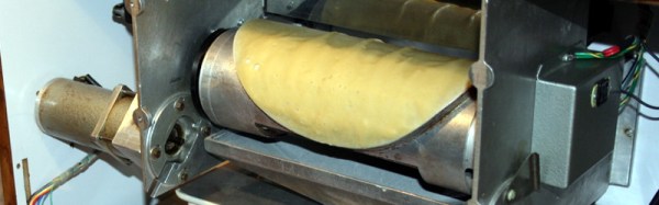
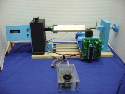 Next up is [castvee8] who has entered the 2016 Hackaday Prize with Building Simplified Machinery. Over the years, [Castvee8] has built a few 3D printers and CNC machines. These projects always start with buying the same parts over and over: ground rods, linear bearings, stepper motors, drivers, etc. [Castvee8] is trying to build 3D printed machines which use as few of these vitamins as possible, yet are still strong enough to work in wood, plastic, wax, foam, and other light maker-friendly materials. So far the simple, modular components and electronics have led to a mini mill, mini lathe, and a drill press for things like printed circuit boards. Keeping things low-cost will make these tools accessible to everyone.
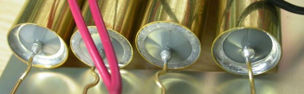
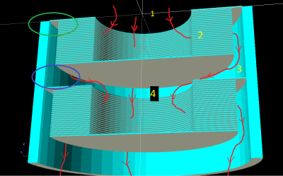 [Keegan Reilly] entered Everyman’s turbomolecular pump. Vacuum pumps are great, but everyone knows the real fun starts around 10^-7 Torr. Pulling things down this low requires a specialized pump. Two common designs are oil diffusion pumps and Turbomolecular pumps. Oil diffusion is cheap, but not everyone wants a hot vat of oil bubbling away in their vacuum chamber. Turbomolecular pumps are much cleaner, but very expensive. [Keegan] is attempting to design a low-cost version of a turbomolecular pump. He’s trying to use Tesla’s bladeless turbine design rather than the traditional bladed turbines used in commercial pumps. So far tests using a Dremel tool and paper discs have been promising – nothing has exploded yet!
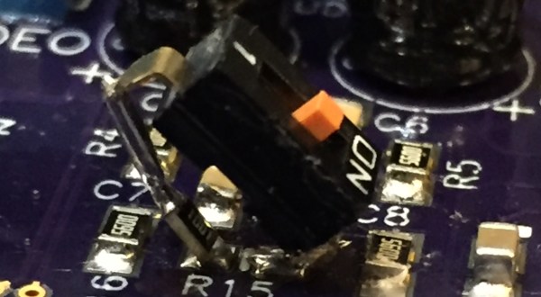
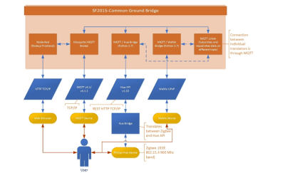 Finally, we have [Samuel Bowman] with Seamless IoT Protocol Translation: Common Ground. Love it or hate it, the Internet of Things is going to be here for a while. Every device seems to speak a different language though . Z-wave, Zigbee, LoRa, WiFi, and a host of other protocols, all on different frequencies. Some are frequency hopping, some use mesh networks. [Samuel] is trying to design one device to translate between any of the emerging standards. Common Ground started as a science fair project connecting MQTT to Phillips Hue devices. Once [Samuel] achieved that goal, he realized how much potential there is in a universal translator box. We’re hoping [Samuel] achieves his goals quickly – it seems like new IoT standards are being introduced every day.
New projects are entering the 2016 Hackaday Prize every hour! You can see the full list right here. That’s it for the 100th Hacklet. As always, see you next week. Same hack time, same hack channel, bringing you the best of Hackaday.io!