If you work on RF circuits–even if you aren’t a ham radio operator–you ought to have a dummy load. A dummy load is a non-radiative “antenna” with known impedance that you can use to test your RF circuit without radiating. For radio work, you usually just need a 50-ohm resistor that is non-inductive (at least at the frequencies you are interested in) and that can dissipate the amount of power you’ll expect it to handle (at least for a short time). [VO1PWF] wanted a dummy load and built his own.
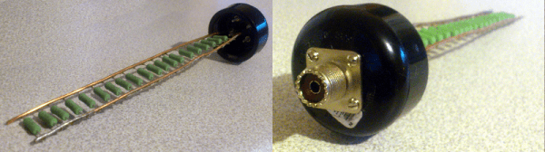
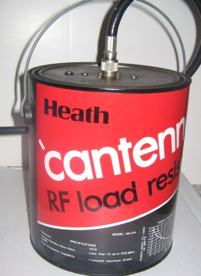 The Cantenna (not the Pringle’s kind; see right) was a famous dummy load design when Heathkit was in business. It was a single carbon rod immersed in a paint can full transformer oil (which we now know was full of dangerous PCBs; and we don’t mean printed circuit boards). [VO1PWF’s] design is a little more practical, using some resistors in parallel (20 1K resistors), a plastic pipe housing, and mineral oil to keep it all cool.
The reason for the parallel resistors is to maximize the power handling capability. The resistors are 3W units, so the dummy load–in theory–can handle 60 watts. Often, high power resistors are wire wound and thus have a good bit of parasitic inductance that makes the dummy load reactive (not a good thing since that makes the load impedance vary by frequency). They do make non-inductive wire wound resistors, but these aren’t truly non-inductive. The wire winds in two different directions, so the inductance tends to cancel out. We wouldn’t trust them to be a pure resistance in a high-power dummy load design.